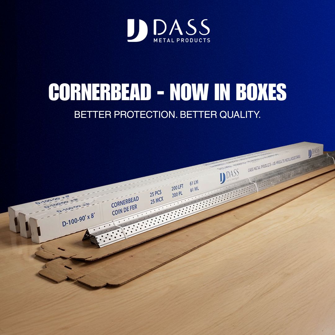
Bridging channel framing is the continuous lateral bracing strategy that keeps cold-formed steel stud walls straight, reduces vibration, and helps members achieve their intended structural and service performance. Whether you’re building non-load-bearing partitions or tall, load-bearing curtain walls, correctly planned and installed bridging channels and their clips tie the stud line together so each member isn’t left to deflect or twist on its own.
What bridging channel framing is
In metal stud construction, a bridging channel is a cold-formed steel section run perpendicular to the studs to restrain the stud flanges from rolling or buckling laterally. When attached with purpose-made clips or fasteners, these channels distribute forces among multiple studs and provide a continuous line of restraint. The result is:
- Improved in-plane and out-of-plane stability of studs
- Reduced risk of flange local buckling and stud rotation under load
- Straighter walls for better drywall finish quality
- Less perceptible vibration in tall or long-span partitions
You may also hear related terms on drawings and in the field:
- Bridging: The general act of tying studs together laterally.
- Carrying channel: A heavier channel often used overhead to support furring channels or ceilings; it can also serve as a robust bridging line in some wall applications when specified.
- Resilient channel: An acoustic decoupling member for gypsum board. It is not a substitute for structural bridging unless explicitly engineered.
Why bridging matters in steel stud walls
Individual cold-formed studs are slender and efficient. That efficiency comes with a trade-off: without restraint, their flanges can displace laterally well before the stud reaches its theoretical capacity. Bridging channel framing addresses this by clamping flanges in position along the height of the wall. Done right, it enables the stud line to behave as the design intended.
Practical outcomes of correct bridging include:
- Dimensional stability: Keeps drywall joints tight and corners crisp, reducing touch-ups.
- Load path reliability: Helps the stud meet specified load tables by mitigating lateral-torsional effects.
- Serviceability: Damps vibration and “drumhead” response from wind or footfall on adjacent floors.
- Compatibility: Provides predictable attachment points for insulation retainers, MEP support ties, and backing.
Because local codes, engineering specifications, and manufacturer requirements vary by application, treat bridging as a designed system—not a field improvisation.
Components and terminology you’ll see on drawings
- Bridging/carrying channel: Typically a cold-formed steel channel section sized to the stud height and loads. The profile and gauge are as specified by the design.
- Bridging clips: Preformed connectors that fasten the channel to the stud flanges. Clip geometry and screw count are specified to transfer bracing forces without deforming the stud web.
- End anchorage: The method of terminating channel runs at corners or abutments (e.g., angle clip or stud return) so the line of bracing is continuous.
- Splice detail: Overlap or connector type that joins channel lengths to act as one continuous member.
- Deflection interfaces: If the top of wall uses slotted deflection track, bridging near the head must not lock the stud to the structure; connection details account for vertical movement.
Layout, spacing, and planning the bridging lines
There isn’t a one-size-fits-all spacing for bridging. It depends on stud height, gauge, load direction, and project requirements. Use the project’s structural notes and submittals to determine quantity and placement. As a planning framework:
- Confirm design intent: Check wall types, stud sizes/gauges, and notes calling for “continuous lateral bracing” or “bridging channel.” Identify acoustic walls that use resilient components so you don’t inadvertently short-circuit them.
- Mark elevations: On tall walls, it’s common to see multiple lines of bridging. Snap lines on studs for consistent heights.
- Coordinate MEP: Place bridging to avoid major conduit and duct paths. Where conflicts are unavoidable, use engineered alternate clip locations as permitted by the design.
- Plan splices and terminations: Keep splices staggered and away from high-congestion zones; ensure end anchorage at corners and returns.
Field-proven installation sequence
The following sequence is a generalized process outline. Always follow the project’s approved details and product documentation.
- Pre-check studs: Verify studs are correctly seated in track, plumb within tolerance, and oriented consistently.
- Cut and stage channel: Precut channel lengths to fit between corners or control joints with planned splice overlaps. Deburr cut edges.
- Install first clip: Start at a corner or fixed end. Attach a bridging clip to the stud flange at the marked elevation per the specified fastener size and count.
- Thread channel: Feed the channel through successive clips down the line. Keep the open face of the channel oriented as shown in the detail.
- Fasten progressively: With the channel supported, fasten each clip to the channel before moving to the next stud. Do not preload or camber the channel; keep it straight and level.
- Handle splices: Overlap or connect channel pieces using the specified splice method, maintaining continuity and alignment. Tighten all fasteners to the specified torque or seating condition.
- Terminate properly: At the far end, install the end anchorage detail. Recheck that the entire run is continuous with no skipped clips.
- Repeat additional lines: For multiple bridging lines on tall walls, repeat at each elevation, checking vertical alignment.
- Final verification: Sight down the wall for straightness, then measure sample stud flange positions to confirm restraint.
Carrying channel vs. bridging channel
Carrying channel and bridging channel are sometimes used interchangeably in conversation, but they serve different typical roles:
- Bridging channel: Primarily for lateral restraint of studs within a wall.
- Carrying channel: Often a heavier section in ceiling systems to carry furring channels and support finishes; it can double as a robust bracing line in walls only when specified to do so.
Follow the drawings: don’t upsize or substitute sections without approval, as it can affect interfaces with clips, deflection allowances, and acoustic performance.
Acoustics, resilient elements, and interfaces
Acoustic wall types may include resilient components to isolate gypsum board from the stud framing. In those assemblies, indiscriminate bridging can create rigid paths that reduce acoustic isolation. Keep these principles in mind:
- Respect any specified resilient elements by following the detail precisely.
- Do not replace acoustic components with structural bridging unless the design calls for it.
- Where both lateral restraint and acoustic isolation are required, the detail will show how to achieve restraint without creating rigid short-circuits.
Quality checklist for bridging channel framing
- Continuity: Each bridging line is continuous between terminations with correct splice details.
- Clip compliance: Specified clip type and fastener schedule used at every stud.
- Alignment: Channel runs straight and level; no twist induced into stud flanges.
- Movement: Head-of-wall details preserve required vertical deflection capacity where specified.
- Compatibility: No conflicts with MEP runs or firestopping that compromise either system.
- Documentation: Field records show locations, counts, and any approved deviations.
Common mistakes to avoid
- Skipping clips: Leaving a stud unbridged in a run creates weak links and can telegraph as a wavy wall.
- Improvised substitutions: Swapping in unapproved channel sizes or ad-hoc angles may underperform or interfere with other systems.
- Locking movement joints: Fastening bridging in a way that pins a deflection head defeats the purpose of slotted tracks.
- Overtightening fasteners: Crushing thin flanges reduces capacity and can lead to local buckling at the clip.
- Misplaced elevations: Inconsistent line heights reduce the effectiveness of lateral restraint and complicate drywall installation.
Coordination, submittals, and field verification
Successful bridging channel framing starts before materials arrive on site:
- Shop drawings: Ensure they call out the count and elevation of each bridging line, clip types, splice details, and termination methods.
- Product data: Keep manufacturer literature and any load tables relevant to the chosen studs and channels on hand for inspection.
- Preinstallation meeting: Align field crews, GC, and MEP trades on sequencing and clearances.
- Mockups: For complex or high-performance walls, a short mockup bay can validate layout, fastener patterns, and interfaces.
During installation, periodic checks by supervision help catch skipped clips, misalignment, or conflicts early. After completion, document the work with photos and markups that reflect the as-built locations of bridging lines—especially useful when future penetrations are planned.
Troubleshooting symptoms and likely causes
- Wavy or uneven gypsum: Verify studs are braced per plan; check for missing clips or misaligned channels.
- Audible rattle under wind or door slams: Confirm bridging continuity and fastener seating; look for long unbraced stud segments.
- Cracked joints at head-of-wall: Ensure bridging does not restrain a deflection head and that finish details allow movement.
- Clip dimpling or deformation: Review fastener size/count and verify channel orientation and gauge match the approved submittal.
FAQ
Is resilient channel the same as bridging channel framing?
No. Resilient channel is primarily an acoustic element used to decouple gypsum board from framing. Bridging channel framing is a structural restraint system for studs. They serve different purposes and are not interchangeable unless the design explicitly allows it.
How many lines of bridging do I need on a tall wall?
The required number and spacing are project-specific and should come from the structural design and approved submittals. Taller walls and heavier loads typically demand multiple lines at defined elevations. Do not assume a standard spacing without confirmation.
Can I place bridging near the head of wall if a deflection track is specified?
Yes—if the detail provides for vertical movement. Use the specified clips and connection methods that maintain the required deflection gap. Avoid any fastener that would rigidly tie the stud to the structure across a movement joint.
What’s the best way to coordinate bridging with MEP runs?
Lay out bridging elevations early and share them with MEP trades. Where conflicts exist, consult the design team for acceptable alternate elevations or clip arrangements that preserve structural intent without obstructing services.