If you work in framing, drywall, or specification, you make constant choices about members, gauges, tracks, channels, and accessories. This reference collects the essentials on canadian steel studs so you can move from intent to a buildable, coordinated package—covering sizing, gauge selection, tracks and channels, acoustics, deflection, and submittal-ready documentation.
How steel studs are classified
Cold-formed steel studs are roll-formed members identified by their web (depth), flange (leg width), and return or lip. In practice, you’ll see designations that map to nominal depths (for example, a 3-5/8 inch or 92 mm web) and common flanges (1-1/4 inch or 32 mm, among others). Two broad categories drive most choices:
- Non-load-bearing (light gauge) – Interior partitions and ceilings where studs primarily serve as framing for gypsum board and services.
- Load-bearing (heavy gauge) – Exterior or structural walls, tall interior walls, shaftwalls, and openings that transfer gravity and lateral loads.
Beyond geometry and gauge, studs and tracks are commonly supplied galvanized for corrosion resistance. Channels, clips, and trims round out the system so walls meet alignment, service, acoustic, and finish requirements.
Selecting sizes and gauges
Choosing the right combination of depth and gauge starts with wall height, service requirements, finish layers, and whether the wall is load-bearing. Use this step-by-step approach to narrow options before you consult load tables and project documents.
- Define wall function
- Interior, non-load-bearing partitions: prioritize serviceability, acoustic targets, and finish flatness.
- Load-bearing or tall partitions: check axial, bending, and deflection criteria; consider composite action with sheathing where applicable.
- Match web depth to wall height and services
- Shallow depths (e.g., 2-1/2 in / 64 mm) for low partitions or chase walls.
- Standard depths (e.g., 3-5/8 in / 92 mm; 6 in / 152 mm) for typical partitions, MEP routing, and insulation batts.
- Deeper members for tall walls, higher STC assemblies, or exterior sheathing planes.
- Select gauge by structural and service limits
- Light gauge for common interior partitions at standard heights.
- Heavier gauge for increased spans, openings, higher loads, or impact zones.
- Set stud spacing
- 16 in or 24 in on center are typical patterns. Taller walls, heavier finishes, or high-traffic areas may justify tighter spacing.
- Confirm deflection and drift allowances
- Where floors/roofs deflect or frames drift, pair studs with compatible deflection tracks and clips to avoid unintended load transfer to finishes.
With these preliminaries, review manufacturer load tables, check fastener schedules, and coordinate with the project’s structural and architectural requirements before finalizing the submittal.
Tracks, channels, and accessories
A steel stud framing system is only as good as the tracks, channels, and connectors that stabilize, align, and finish it. Here is a concise rundown of commonly specified components and where they fit:
- Standard track – The baseline U-shaped member that captures studs at the head and base of walls, jambs, and bulkheads.
- Deep track – Taller legs help with alignment, tolerance take-up, and added fastening edge; useful on tall walls or where substrate flatness varies.
- Slotted deflection track – Pre-slotted or configured to allow vertical movement of studs relative to structure, protecting gypsum finishes from compression or cracking.
- Bridging / carrying channel – Lateral bracing for studs to meet buckling and vibration limits; also used as carrying members above ceilings.
- Resilient channel – Decouples gypsum board from framing to reduce sound transmission; typically installed perpendicular to studs.
- Furring channel – Creates a level plane for finishes, backs veneers, and accommodates services or insulation.
- Windbrace – Diagonal bracing or strap elements that add racking resistance within non-sheathed frames.
- U-Flex track – A flexible track profile for framing curves and radiused partitions without segmented cuts.
- Clips and connectors
- Deflection side clip – Connects studs to structure while permitting in-plane or vertical movement.
- Webslide clip – Adjustable connection to accommodate layout tolerances or minor field shifts.
- Bridging clip – Attaches bridging channels to studs for lateral bracing.
- Shaftwall / CH stud – Specialty studs for elevator, mechanical, and shaft enclosures using board-and-stud systems.
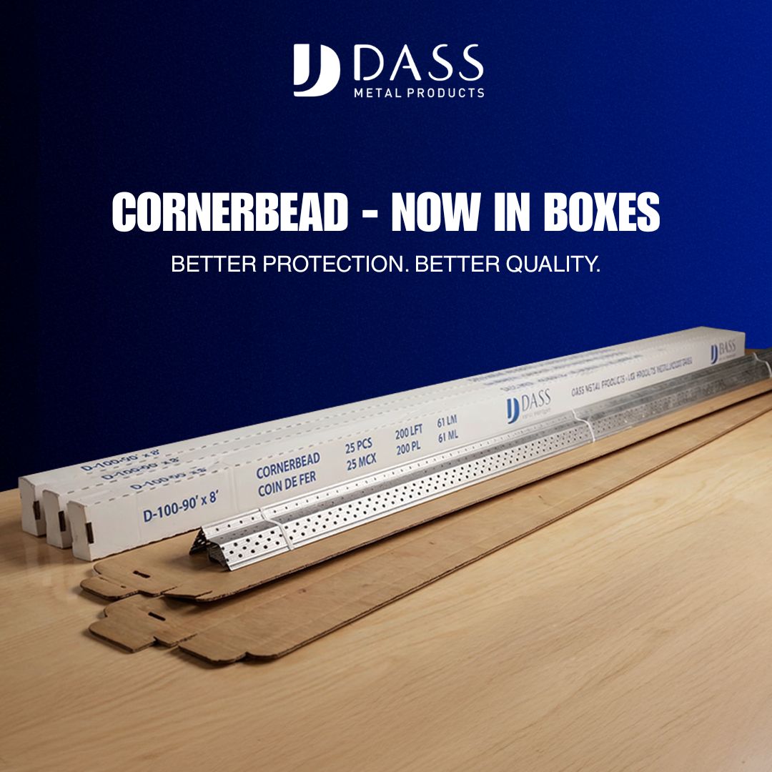
- Drywall finishing sections – 90°/130° cornerbead for corners, plus L trim, J trim, and J track to terminate boards and protect edges.
- Angles, flats, and wire – Utility angles, flat strips, tie wire, and hanger wire for strapping, support, and suspension tasks.
- Z-Bar and L track – Common attachment profiles for furring, veneers, and claddings to establish plumb, ventilated finish planes.
Choosing among these depends on performance targets: deflection accommodation, bracing needs, acoustic isolation, finish durability, and field tolerance. Coordinate details so that each component contributes to the same design assumptions used in calculations and assembly ratings.
Acoustics and fire considerations
Partition performance is often defined as much by connectors and layering as by stud gauge. Two themes dominate coordination:
- Acoustics – Resilient channel, double-stud or staggered-stud layouts, insulation type, and board layering all influence airborne sound (and impact on flanking paths). Penetrations, back-to-back boxes, and continuous framing can short-circuit your intent, so treat electrical/mechanical coordination as part of the acoustic design.
- Fire – Stud selection, track type, board thickness/number of layers, joint treatment, and perimeter conditions affect fire-resistance ratings. Use listed assemblies that match the intended configuration and follow installation details precisely.
Where assemblies have jurisdictional requirements or where life-safety is implicated, consult the project’s registered design professionals and follow the specified, listed systems. This article does not provide professional design services or code interpretations.
Installation basics and good practices
Field execution must align with the performance assumptions in your specifications and calculations. These practices help keep layout predictable and finishes flat:
- Layout and preparation
- Snap lines and verify plumb/level of substrates before anchoring tracks.
- Use standard track, deep track, or slotted deflection track to suit movement and tolerance conditions.
- Stud placement
- Cut or order to length considering required gaps at deflection heads.
- Seat studs fully in track; add bridging / carrying channel and bridging clips per spacing criteria to control twist and vibration.
- Openings and edges
- Reinforce jambs and headers with heavier gauge or back-to-back studs where specified.
- Use appropriate clips to maintain movement capability at heads and sills.
- Boarding and finishes
- For acoustics, install resilient channel on the correct face and orientation; avoid short-circuiting with direct fasteners through the channel flange.
- Use cornerbead, L trim, and J trim to protect and terminate edges; coordinate with finish thicknesses.
Always follow manufacturer instructions for fastener type, spacing, and sequencing. Where structural performance is required, ensure inspection points for bracing, connections, and deflection detailing are clear in the quality plan.
Estimating and submittals
Accurate takeoffs and clear documentation minimize changes downstream. A consistent package generally includes:
- Member schedule – Web depth, flange, gauge, and coating for studs and tracks by wall type.
- Spacing and bracing – On-center spacing, bridging intervals, and clip references.
- Deflection and drift criteria – Required head-of-wall solutions and permitted movement.
- Accessories – Channels (resilient and furring), trims (cornerbead, L/J trims), Z-Bar/L track, and wire/angles/straps.
- Openings – Jamb/header stud configurations and gauges, including built-up members as needed.
- Acoustic and fire assemblies – Assembly IDs or listings, board layers, insulation, and sealants.
- Technical references – Product brochures, load tables (metric and imperial as required), standards references, and MSDS documentation.
- Quality controls – Hold points, inspection checklists, and submittal review sequences to align shop drawings with field conditions.
For cross-border or multi-region projects, maintain a single baseline schedule and note regional substitutions transparently to avoid conflicts during procurement and inspection.
Common mistakes to avoid
- Omitting deflection detailing – Using standard track where building movement is expected can telegraph cracks into finishes; use slotted deflection track or approved clips where required.
- Under-bracing tall studs – Skipping bridging / carrying channel at the specified intervals can lead to out-of-plane movement and finish irregularities.
- Short-circuiting acoustics – Fastening gypsum through resilient channel flanges into studs, misplacing back-to-back boxes, or leaving unsealed perimeters undermines STC targets.
- Mismatched gauges at openings – Headers and jambs often need heavier gauge or paired studs; align takeoffs with door and glazing schedules.
- Ignoring corrosion exposure – Select coatings appropriate to interior, exterior, or moisture-prone locations.
- Inconsistent submittal language – Mixing nominal and actual dimensions or switching metric/imperial without clarity invites field errors.
Product selection checklist
Use this quick checklist during design development, precon, and procurement:
- Wall function: non-load-bearing vs. load-bearing; interior vs. exterior.
- Assembly height, finish layers, and required deflection/drift allowances.
- Stud web depth, flange width, gauge, and spacing.
- Head/base conditions: standard, deep, or slotted deflection track.
- Bracing: bridging/carrying channel type and interval; bridging clips.
- Acoustics: resilient channel use, insulation type, and flanking controls.
- Openings: jamb/header gauge and built-up requirements.
- Accessories: furring channel, Z-Bar, L track, trims (90°/130° cornerbead, L/J trims, J track).
- Specialty: shaftwall/CH studs where required.
- Documentation: brochures, load tables (metric/imperial), standards, MSDS.
FAQs
What gauges are typical for interior non-load-bearing walls?
Light gauge members are commonly used for standard-height interior partitions. The final gauge depends on wall height, on-center spacing, finish weight, and any impact or abuse requirements. Always confirm against manufacturer load tables and the project specification.
When do you need slotted deflection track?
Use slotted deflection track when the structure above is expected to move relative to the partition—such as floor or roof deflection—so that studs and gypsum finishes are not loaded unintentionally. Pair the track with compatible fastener patterns and, where needed, deflection clips at jambs and heads.
How is resilient channel different from furring channel?
Resilient channel is designed to decouple gypsum boards from framing to improve acoustic performance; it has a geometry and fastening pattern that limits direct vibration transfer. Furring channel primarily creates a level substrate or service cavity for finishes and does not, by itself, provide the same degree of acoustic isolation.
Can steel studs be used on exterior or structural walls?
Yes, heavy gauge, load-bearing studs can be used for exterior or structural applications when designed accordingly. Selection involves structural checks for axial and lateral loads, bracing requirements, deflection limits, and coordination with sheathing and façade systems. Consult the project’s structural engineer for final design.