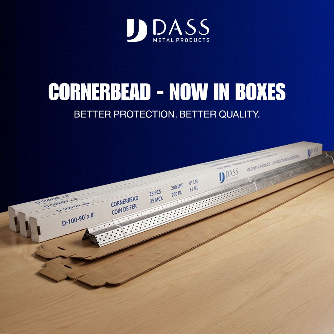
Drywall trim is compatible only when the profile fits the board thickness and edge condition, the attachment method suits the substrate, and the surrounding framing leaves the required clearance. Dass Metal identifies L Trim for 1/2-inch and 5/8-inch drywall, while J Trim is used at gypsum-panel junctions with contrasting surfaces. Confirm the complete assembly before ordering or installing.
Start With the Four Compatibility Questions
Do not choose drywall trim by profile name alone. Check these four interfaces in order:
- Profile to condition: Does the trim match an exposed perimeter, covered cut edge, corner, opening, reveal, channel, or unusual transition?
- Trim to board: Does the profile accept the actual gypsum-board thickness, including any required finish build-up?
- Attachment to substrate: Can the selected attachment method work with the surface behind or beside the trim?
- Trim to framing assembly: Does the trim clear studs, tracks, furring channels, resilient elements, clips, and deflection components while preserving the intended movement?
The first two questions establish product compatibility. The last two establish installation compatibility. A trim can fit the board and still fail because the substrate is unsuitable, the fastener has nowhere appropriate to land, or a movement detail has been made rigid.
At the specification stage, review the edge condition together with the surrounding framing. Studs, channels, resilient elements, and deflection tracks can interfere with trim attachment or reduce the clearance needed for the finish. Dass Metal’s guidance on drywall finishing trims also calls for checking these interfaces before installation.
Match the Profile to the Edge, Corner, Opening, or Reveal
The profile should solve the geometry of the termination first. The following matrix is a starting point, not a substitute for the project detail or product information.
| Condition | Likely profile direction | What to verify |
|---|---|---|
| Exposed drywall perimeter with a square, visible edge | L Trim | Board thickness, flange coverage, exposed edge alignment, and attachment access |
| Gypsum panel ending at a column, window mullion, or contrasting surface | J Trim | Insertion or reveal depth, adjacent material thickness, opening dimensions, and finish interface |
| Outside corner formed by two board faces | Corner bead or a specified corner profile | Corner angle, board edges, impact exposure, flange coverage, and finishing method |
| Inside corner or change of plane | Specified inside-corner, angle, or joint treatment | Movement, joint position, finish build-up, and whether the condition is a true corner or a control joint |
| Intentional shadow line or recessed reveal | Reveal profile or special profile | Reveal depth, width, straightness, adjacent board support, and continuity through corners |
| Termination beside a track, channel, or other framing component | Profile selected from the complete assembly detail | Clearance, fastener access, movement, acoustic separation, and interference from the component |
| Unusual transition between dissimilar materials | J Trim, L Trim, reveal, or custom profile depending on geometry | Relative movement, surface condition, finish compatibility, and approved attachment method |
L Trim is identified as compatible with both 1/2-inch and 5/8-inch drywall. Its perforations and textured surface support joint-compound adhesion, and the listed installation options include nails or screws. That does not make every L Trim detail interchangeable: the board edge, substrate, flange position, and finish still need to be checked.
J Trim is used where a gypsum panel meets a contrasting surface such as a column or window mullion, and at other wallboard terminations. It suits conditions that need an inserted or dropped reveal, while L Trim generally suits a perimeter that needs a square, visible edge. Treat these as different functions, not two names for the same profile.
Do not assume that a 3/8-inch board, a thicker specialty board, or a layered assembly will fit either profile. If the board thickness is outside the verified product information, obtain the applicable dimension and compatibility confirmation before release.
Check Board Thickness and Supported Edges Before Ordering
Board thickness affects how the trim sits against the gypsum edge, where the flange lands, how much compound is needed, and whether the finished edge appears flush or proud. A profile that fits a single board layer may not fit a double layer or a board combined with another finish material.
Record the actual board build-up, not just the nominal wall type. Include each gypsum layer, tile backer or other facing where relevant, the expected compound or finish thickness, and the visible edge dimension. Then compare those measurements with the selected trim profile.
Support is a separate check from trim fit. In the fire-performance context stated in Ontario’s 2024 Building Code Compendium, gypsum board installed over framing or furring must have its edges supported, subject to the specific exception described for 15.9 mm Type X board installed horizontally under the listed framing condition. Review the applicable assembly in Ontario’s fire-performance provisions before treating a trim or edge detail as complete.
Trim should not be used to compensate for missing framing, an unsupported board edge, or an unapproved change to a rated assembly. If the trim needs to bridge a gap, confirm that the detail is designed to do so and that the finish system accepts the resulting geometry.
Match the Attachment Method to the Substrate
The substrate controls whether adhesive, mechanical fastening, joint compound, or a combination can be used. First identify what the trim actually contacts: bare gypsum board, painted drywall, wood, MDF, plaster, masonry, concrete, tile, or a metal framing component.
| Substrate or contact surface | Compatibility questions | Practical review |
|---|---|---|
| Bare gypsum board | Does the trim flange sit flat, and is the board edge sound? | Remove loose material, dry-fit the profile, and confirm the finish can cover the flange without leaving a proud edge. |
| Painted drywall | Will the attachment bond to the paint film or to the underlying board? | Check that the coating is sound, clean, and suitable for the specified attachment method. Do not treat an unknown paint layer as a reliable substrate. |
| Wood or MDF | Is the surface stable, flat, and able to accept the selected fastener or approved adhesive? | Account for movement, edge distance, surface coatings, and the possibility that the trim and substrate move differently. |
| Plaster | Is the plaster firmly attached, or is the surface dusty, friable, or uneven? | Inspect for hollow or loose areas and resolve surface condition before selecting the attachment route. |
| Masonry or concrete | Can the specified attachment method work with the hardness, porosity, and surface profile? | Confirm surface preparation, fastener type, dust control, and any required backing or adhesive evaluation. |
| Tile or finished cladding | Does the trim need to sit over, beside, or inside the finish? | Measure the finished thickness and joint geometry. Check whether drilling, bonding, or a reveal detail is permitted by the assembly. |
When adhesive may be part of the solution
Adhesive can be appropriate only when the product, surfaces, loading, movement, and installation conditions support it. Cleanliness, soundness, flatness, working time, cure support, moisture, and temperature all affect the result. A general adhesive recommendation is not proof that the same product works for every metal trim and substrate.
The supplied CCMC evaluation identifies third-party or CCMC-evaluated adhesive requirements for the specific drywall-to-framing application described in that document. That requirement should not be generalized to painted walls, masonry, tile, plaster, MDF, or every trim profile. Use the adhesive and attachment requirements stated for the actual project and assembly.
When mechanical fastening or a combined method needs review
Mechanical fastening may be relevant where the trim has a suitable backing, the fastener can be placed without damaging the board or interfering with services, and the specified method permits it. Dass Metal lists nails or screws as installation options for its L Trim, but the appropriate fastener, spacing, penetration, and sequence remain project-specific.
A combined method can address different needs, such as positioning with one method and securing the profile while the finish or adhesive cures with another. Do not select the combination by habit. Confirm that the methods do not create a visible bump, bridge a movement joint, damage an acoustic separation, or conflict with the finishing specification.
Dry-fit every transition before applying an attachment product. The trim should sit where the finished edge, reveal, or corner is intended to be, with no forced bend caused by an uneven substrate.
Coordinate Trim With Steel Framing and Movement Details
Interior framing adds compatibility issues that are easy to miss on a trim-only drawing. A stud flange, track leg, furring channel, resilient channel, clip, or deflection track can change where the trim sits and whether a fastener can be installed without creating an unwanted connection.
- Studs and tracks: Confirm that the trim flange does not collide with the framing flange or lose the backing needed for attachment.
- Furring channels: Check the finished plane and whether the trim must span or terminate at a change in support.
- Resilient channels and clips: Keep the trim and its fasteners from creating a rigid bridge through an acoustic separation.
- Deflection tracks: Preserve the designed movement and head-of-wall clearance. A rigid trim, fastener, or compound bridge can defeat the movement detail.
- Drywall returns: Measure the return depth and sequence the trim with the adjacent board, frame, window, or door component.
- Dissimilar materials: Account for different surface textures, movement, thicknesses, and finish requirements at the junction.
Fit is not the same as performance. Fire-rated and sound-rated results belong to the complete wall or ceiling assembly, including board, framing, fasteners, joints, penetrations, perimeter details, and movement provisions. Ontario’s fire and sound resistance tables also address the finishing of gypsum-board joints in the stated contexts, so the trim detail must remain consistent with the approved assembly. Review the applicable fire and sound resistance requirements instead of assigning a rating to the trim alone.
Three Hypothetical Compatibility Checks
1. Exposed 5/8-inch drywall perimeter
Condition: A 5/8-inch gypsum panel ends at an exposed perimeter where the finished edge must remain square and visible.
Profile direction: L Trim is a plausible starting point because Dass Metal identifies it for 1/2-inch and 5/8-inch drywall and describes a square visible-edge application.
Checks: Confirm the actual board edge, flange coverage, substrate behind the flange, and access for the listed nail or screw installation options. Dry-fit the trim to check that the finished compound will not leave the edge proud. Verify that the perimeter does not border a movement or acoustic separation that the attachment would bridge.
2. Gypsum panel at a window mullion or column
Condition: A gypsum panel terminates at a window mullion or column made from a contrasting material.
Profile direction: J Trim is the relevant profile direction because it is used at gypsum-panel junctions with contrasting surfaces and other wallboard terminations.
Checks: Measure the mullion or column face, the panel thickness, the desired reveal, and the available attachment surface. Confirm whether the trim is inserted into a recess, dropped against the surface, or intended to create a visible separation. Review the finish interface so compound, sealant, or adjacent coating does not close the intended reveal.
3. Trim beside a channel or deflection detail
Condition: A drywall edge meets a transition near a furring channel, resilient element, clip, or deflection track.
Profile direction: No profile should be released from the trim name alone. Select the edge or reveal profile only after the framing detail shows the finished plane, clearance, support, and movement path.
Checks: Mark the movement zone, identify every component that must remain independent, and confirm where attachment is permitted. Check that the trim, fasteners, joint compound, and adjacent finish do not bridge the separation. Resolve the detail in the submittal before installation, not after cracking or acoustic short-circuiting appears.
Specify the Complete Trim Interface
A reviewable quote request or submittal should describe the interface, not just ask for “metal drywall trim.” Include:
- Project drawing and detail reference.
- Profile type and intended function, such as exposed perimeter, opening termination, corner, reveal, or transition.
- Trim dimensions, material, finish, and any required perforated or textured flange.
- Gypsum-board thickness, number of layers, and finished build-up.
- Substrate material and surface condition at the attachment line.
- Corner, edge, opening, return, channel, or dissimilar-material geometry.
- Attachment method required or permitted by the project documents.
- Clearance from studs, tracks, furring, clips, resilient elements, and deflection components.
- Movement, acoustic, fire-performance, or other assembly constraints.
- Compatible accessories, connectors, backing, joint treatment, and finish interface.
- Sample, mock-up, storage, handling, examination, and installation-record requirements.
- Responsibility for reviewing and approving the final profile and detail.
Before approval, verify the profile, dimensions, material, edge condition, board thickness, finish interface, and compatible framing components. Dass Metal’s steel-framing submittal checklist uses these same categories to help prevent a component from being approved in isolation.
Specifications sometimes include detailed requirements for material, coating, perforations, base thickness, or standards. For example, one supplied Canadian project manual specifies zinc-coated metal trim with perforated flanges and a 0.5 mm base thickness to ASTM C1047 for its stated project. Treat that as a project-specific example, not a universal requirement for every drywall trim order.
Troubleshoot by Visible Symptom
| Symptom | Compatibility checks |
|---|---|
| Trim is loose or debonding | Inspect the substrate for dust, paint failure, moisture, friable material, unevenness, or an attachment method that was not approved for the surface. Check whether movement or insufficient cure support is loading the trim. |
| Cracking appears beside the trim | Check board support, joint location, profile fit, movement at the junction, rigid bridging across a deflection detail, and whether the finishing sequence matches the assembly. |
| Compound does not adhere well | Inspect the flange material and surface, contamination, profile texture or perforation, compound compatibility, and whether the flange is clean and properly positioned. |
| The edge is exposed, proud, or uneven | Recheck board thickness, flange depth, substrate flatness, corner geometry, and finish build-up. A profile selected for a thinner board or different edge can produce a visible mismatch. |
| The reveal is too shallow, deep, or inconsistent | Measure the profile and adjacent material together. Check the recess depth, return dimension, board position, corner continuity, and whether compound or sealant has reduced the intended opening. |
These symptoms do not prove a product defect. Inspect the complete interface, compare the installed condition with the approved detail, and identify whether the cause is profile selection, substrate preparation, attachment, movement, support, or finishing.
Make the Project Handoff in the Right Order
Classify the condition first. Then verify the board thickness, inspect the substrate, coordinate framing and movement, choose the attachment route, and document the finish interface. This sequence keeps a physically suitable profile from being installed in an unsuitable assembly.
To review Dass Metal Products’ drywall finishing sections, visit its drywall finishing sections.
Frequently Asked Questions
Can L Trim and J Trim be used interchangeably?
No. L Trim is suited to a square, visible perimeter, while J Trim is used at gypsum-panel junctions with contrasting surfaces and conditions that may need an inserted or dropped reveal. Select by geometry and finish intent, then verify the board thickness and attachment detail.
What should I verify when drywall trim meets a deflection track or resilient channel?
Verify the finished plane, board support, required clearance, permitted fastener locations, movement path, and acoustic separation. The trim, fasteners, compound, and adjacent finish must not unintentionally create a rigid bridge or restrict designed movement.
Can adhesive alone be used to attach drywall trim?
Only when the project and product documentation support that method for the actual trim, substrate, loading, movement, and curing conditions. Do not generalize an adhesive requirement from one evaluated drywall-to-framing application to painted walls, masonry, tile, plaster, MDF, or other surfaces.
Does drywall trim change the fire rating or sound performance of a wall?
Trim alone does not establish the fire rating or sound performance. Those outcomes belong to the complete approved assembly, including board support, framing, joints, fasteners, penetrations, perimeter conditions, and movement details.
What information should be included in a drywall trim quote request?
Provide the drawing detail, profile function, dimensions, material, board thickness, substrate, edge or corner geometry, finish interface, attachment method, framing clearance, movement requirements, compatible accessories, quantity, and any sample or submittal requirements. This gives the supplier and project reviewer enough information to evaluate the trim as part of the assembly.