Stud wall steel frame systems are the backbone of modern interior and exterior partitions in commercial and residential projects. Whether you’re planning a non-load-bearing drywall partition or coordinating a heavy-gauge, load-bearing assembly, success comes from understanding the core components, matching profiles to performance needs, and executing with disciplined layout and bracing. This guide offers a practical, step-by-step framework you can apply on any project to plan, specify, and build dependable steel stud walls.
Steel stud wall basics
A steel stud wall is a cold-formed metal framing assembly designed to accept board finishes (e.g., gypsum). The typical system includes:
- Studs (light or heavy gauge) that form the vertical framing.
- Track at the head and base to capture and align studs.
- Bridging/carrying channel and related clips to restrain stud twist and distribute loads.
- Acoustic components like resilient channel when sound isolation is a priority.
- Accessories and trims (e.g., cornerbead, J trim, L trim) for clean drywall terminations and edges.
By mixing profile type, gauge, spacing, and bracing, contractors can tune walls for strength, serviceability (deflection and drift), fire and sound-rated constructions, and finish quality. Coordination with project documents and applicable standards is essential for compliant results.
Component overview
Knowing what each piece does—and when to choose it—simplifies design and installation.
Studs: light vs. heavy gauge
Non load bearing steel studs (light gauge) are common for interior partitions and soffits where the stud is not intended to carry vertical building loads. They are selected for straightness, speed, and compatibility with drywall. Load bearing stud framing (heavy gauge) is used where the stud contributes to structural capacity, such as multi-story framing, tall walls, or concentrated loads. Always follow the project’s structural design for gauge, flange width, and spacing.
Track options
- Standard track products: General head and base track for most partitions.
- Deep track: Provides more engagement with studs and added tolerance at the base or head, helpful for tall walls or uneven substrates.
- Slotted deflection track: Allows the structure above to move independently while the wall remains plumb. The slots accommodate vertical deflection at the head without transferring loads into the studs. Verify deflection requirements in the drawings and coordinate fastener type and location accordingly.
Bracing and restraint
- Bridging / carrying channel: Runs horizontally through stud punch-outs to limit rotation and increase system stiffness. It works with dedicated bridging clips or similar hardware.
- Windbrace: Diagonal metal bracing used to enhance lateral stability of walls subject to wind or other horizontal forces. Follow the engineer’s layout for location and anchorage.
Acoustic and furring components
- Resilient channel: A specialty profile installed between studs and drywall to help reduce sound transmission by decoupling the finish layer. Orientation and fastener placement are critical to preserve acoustic performance.
- Furring channel: Used to create a level plane over uneven substrates and to receive finishes. Also useful for ceilings, chases, and service cavities.
Curves and specialty profiles
U-Flex track enables curved partitions without extensive field notching of standard track. Special profiles may be specified to achieve architectural details or to integrate building services where standard sections are insufficient.
Clips, trims, and finish accessories
- Deflection side clip and webslide clip for connections that permit movement or provide adjustable alignment during installation.
- J track and L track for edge conditions, soffits, and framed terminations.
- J trim and L trim for drywall finishing at edges, reveals, and transitions.
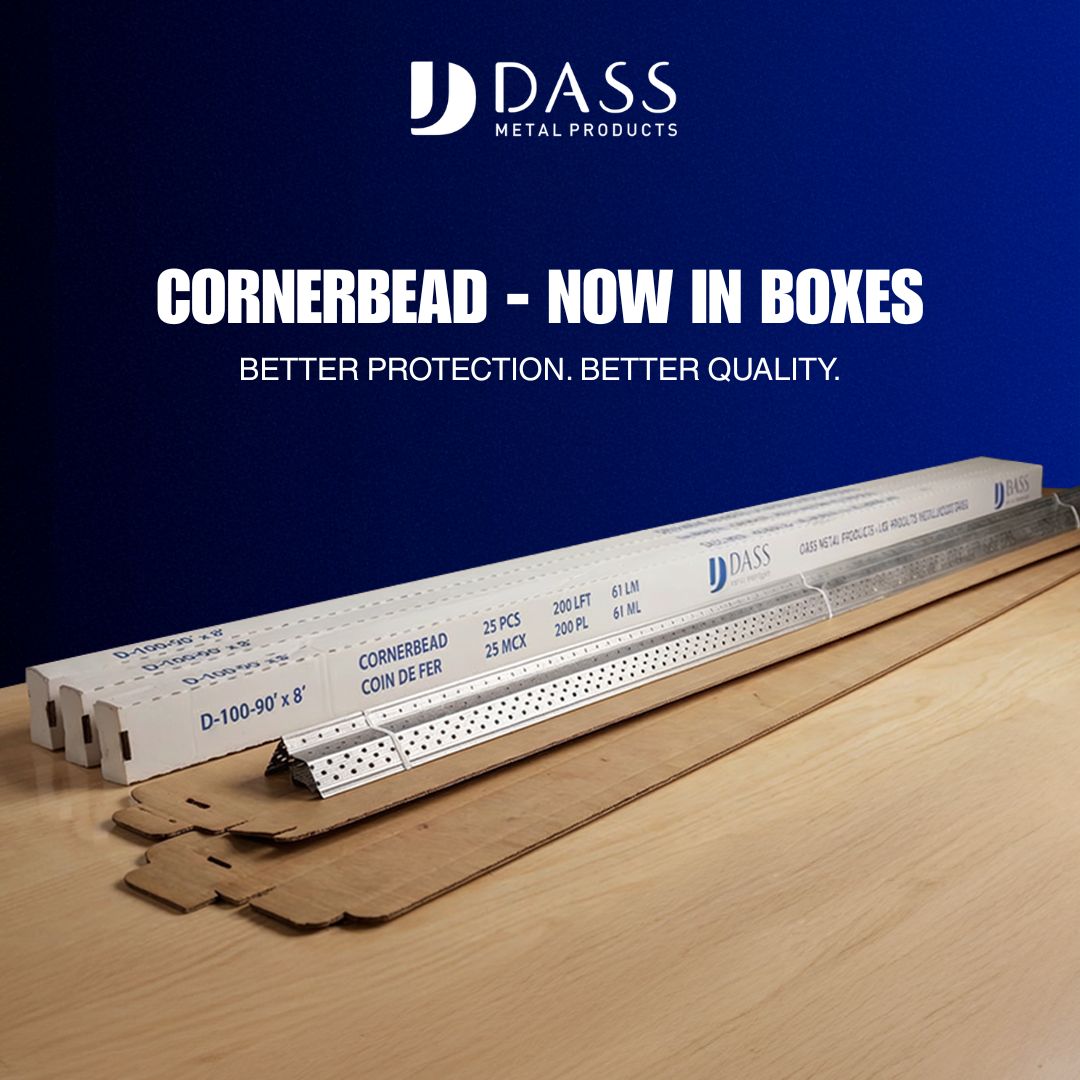
- 90°/130° cornerbead to protect and define outside corners at standard and obtuse angles.
- Z-Bar for specific layering or transition details at finishes.
Ancillary items like tie wire, hanger wire, and flat strips support suspension and fastening needs in ceilings and wall assemblies. Products such as shaftwall / CH stud address vertical shafts and similar conditions—always reference the system details supplied in the project package.
Planning and specification
Effective planning aligns the wall’s purpose with correctly selected components and clear installation intent. Use this framework:
- Define function: Is the wall non-load-bearing or load-bearing? Does it require fire, acoustic, or impact performance? Are there height or span constraints, door frames, or glazed openings?
- Select stud and spacing: Choose light or heavy gauge based on function; set stud spacing (e.g., 16″ or 24″ o.c. as specified). Confirm flange width for board fastening and service routing.
- Choose track type: Standard track for typical head/base; deep track for tolerance; slotted deflection track if head-of-wall movement is indicated.
- Plan bracing: Determine bridging/carrying channel elevation(s), clip types, and any windbrace or additional lateral restraint.
- Acoustic strategy: Evaluate whether resilient channel or furring channel is needed. Confirm board layers, insulation type, and sealant locations in the wall type schedule.
- Openings and edges: Identify trims (J trim, L trim), cornerbead selection, and hardware for reveals, soffits, and transitions.
- Movement and interfaces: For deflection heads, note allowable movement, fastener pattern (into track flanges vs. web), and any slip connectors (e.g., deflection side clip). Address drift or building movement where required.
- Documentation: Verify profiles, gauges, and fasteners against the drawings and referenced standards. Ensure submittals, shop drawings, and product data align.
Field layout and installation
- Prep and layout
- Snap lines for wall location and verify plumb reference points.
- Confirm floor and deck conditions; note any shims or deep track needs.
- Lay out doors, glazing, and penetrations before installing studs.
- Track installation
- Install base track to lines; anchor per specification.
- At the head, install standard or slotted deflection track as designed. Maintain the required clearance for movement if a slip head is used.
- Stud placement
- Cut studs to length allowing for head condition (fixed or slip).
- Insert studs into track; align to spacing marks and plumb each stud.
- Where required, fasten studs to base track; follow head-of-wall fastening rules for deflection tracks.
- Bridging and restraint
- Install bridging/carrying channel at specified heights.
- Attach bridging clips or approved hardware at each stud penetration.
- Install windbrace or additional lateral bracing where indicated.
- Acoustic elements
- Install resilient channel with correct orientation and fastener pattern.
- Avoid short-circuiting the channel with fasteners into studs where the design prohibits it.
- Openings and trims
- Frame openings with appropriate studs and headers as detailed.
- Use J track, L track, J trim, L trim, and cornerbead to create clean, durable edges.
- Quality checks
- Verify stud alignment, spacing, and plumb.
- Confirm deflection gaps and movement details are unobstructed.
- Ensure fastener types, lengths, and patterns match the specification.
Deflection and movement
Building structures move under live load, thermal change, and creep. At the head-of-wall, this can translate to vertical deflection that must not be locked into the partition. Slotted deflection track and deflection side clips are common strategies to allow movement while maintaining alignment.
- Identify the required deflection: The drawings typically state the magnitude and whether it is one-way or two-way.
- Select compatible hardware: Use slotted track or slip connectors designed for the anticipated movement.
- Control fastener placement: Follow patterns that prevent pinning studs to the structure through the slot or slip detail.
- Preserve clearances: Keep head-of-wall gaps free of rigid materials that could bridge movement.
Similarly, interstory drift and thermal expansion joints may require additional detailing. Coordinate with the project team to document all movement interfaces before board installation.
Acoustic considerations
When sound isolation is a goal, design the assembly holistically:
- Structure-borne vs. airborne: Use resilient channel to decouple finishes and reduce direct vibration paths.
- Stud gauge and spacing: Heavier gauges and tighter spacing affect stiffness and resonance; follow the tested wall type when specified.
- Continuity: Avoid unintended rigid connections (e.g., fasteners that bypass resilient components).
- Edges and penetrations: Treat perimeters, back-to-back boxes, and service penetrations carefully; details often govern acoustic outcomes.
Openings, edges, and trims
Clean terminations protect drywall and enhance durability:
- Corner protection: 90°/130° cornerbead provides crisp edges at standard and obtuse corners, resisting impact during use.
- Edge control: J trim and L trim finish exposed board edges, transitions to dissimilar materials, and shadow reveals.
- Soffits and returns: J track and L track frame edges and support returns where board needs a firm termination.
- Layer transitions: Z-Bar helps manage stepped layers or finish transitions as detailed.
For door frames and glazing, coordinate reinforcing studs, headers, and any slip details at the head to maintain required movement or tolerance.
Tall walls and load-bearing
Heavy-gauge load bearing stud framing extends steel stud technology into primary structure. Tall partitions and exterior structural framing demand careful evaluation of:
- Stud selection: Gauge, section depth, and flange width per design.
- Track engagement: Deep track and specified fastener patterns to ensure adequate capture.
- Lateral bracing: Multiple rows of bridging/carrying channel,
windbrace, and clips at intervals defined by the engineer. - Connections: Use designated clips (e.g., webslide clip) where adjustability or slip is required.
- Interfaces: Curtain-wall, slab edges, and deck conditions may require slotted or slip details to handle movement.
Because these assemblies influence primary building behavior, coordinate submittals, shop drawings, and on-site inspections with the project’s structural team.
Materials handling and safety
Proper handling protects straightness and finish quality of steel studs and tracks:
- Store bundles on level supports off the ground; protect from water and corrosive substances.
- Use appropriate lifting methods for bundles; avoid bending members.
- Stage components near their installation area to minimize movement and damage.
- Follow site safety protocols for PPE, cutting, and fastening operations.
Always adhere to the safety plan and the instructions provided in the project documents and product literature.
Quality assurance checklist
- Verification: Stud gauges, track types (standard, deep, slotted deflection), and accessories match the submittal.
- Layout: Wall lines snapped; openings and penetrations coordinated.
- Fastening: Correct screws, spacing, and patterns; no unintended pinning at slip heads.
- Bracing: Bridging/carrying channel elevation and clips installed per plan; windbrace where specified.
- Movement: Head-of-wall gaps clear; deflection clips installed correctly.
- Acoustics: Resilient channel orientation and fasteners verified; no short-circuiting.
- Finishes: J/L trims, J/L tracks, cornerbeads, and Z-Bar installed straight and true.
- Documentation: Field changes recorded; inspections coordinated before close-up.
Frequently asked questions
What is the difference between non-load-bearing and load-bearing steel stud walls?
Non-load-bearing walls use light-gauge studs to support their own weight and finishes but do not carry building loads from above. Load-bearing walls use heavy-gauge studs designed by a structural engineer to support vertical and lateral loads. The drawings will specify which wall types are load-bearing and list gauges, track types, and bracing requirements.
When should I use slotted deflection track?
Use slotted deflection track at the head of wall when the structure above is expected to move relative to the partition. The slots allow the partition to remain plumb while the structure deflects. Confirm the required movement, fastener limitations, and compatible clips in the project details before installation.
How does resilient channel improve acoustic performance?
Resilient channel helps decouple the gypsum board from the studs, reducing direct vibration transfer. Correct orientation and fastener placement are crucial. If the channel is short-circuited with fasteners into studs (where prohibited by the design), the acoustic benefit can be compromised. Follow the tested or specified assembly details for best results.
What role does bridging/carrying channel play in a stud wall?
Bridging/carrying channel provides lateral restraint to studs, reducing twist and increasing overall stiffness. It is threaded through stud punch-outs and secured with compatible clips. Placement elevations and spacing are typically defined in the drawings or engineering notes.
Which trims should I use for clean drywall edges and corners?
Use J trim or L trim to finish exposed edges, soffit returns, and transitions; use 90°/130° cornerbead for outside corners depending on the angle. For framed edges, J track and L track provide crisp terminations and support. Z-Bar can assist with stepped finish conditions where indicated.