The framing bottom plate—also called the steel bottom track—anchors a wall to the floor and aligns studs for straight, code-ready partitions. In 370 New Enterprise Way, Vaughan, ON, Dass Metal Products supplies precision-formed tracks so your framing bottom plate installs quickly, holds true layout, and supports deflection, moisture, and acoustic performance.
By Navjot Dass • Last updated: 2026-05-24
Above-Fold: Hook + What You’ll Learn
Use the bottom plate to lock layout, transfer loads to the slab, and isolate movement. This guide shows you how to choose the right steel track, set accurate lines, fasten to concrete, allow for deflection, and improve sound control—step by step with Dass Metal Products components.
Here’s the thing: wall problems often start at the floor. If the track wanders by 1/8 inch, by the ceiling you can be out by 1/2 inch. We’ll fix that. You’ll get practical steps, tolerances, and checklists that keep crews fast and inspections smooth.
- What a framing bottom plate is and how it works with steel studs
- When to use Standard, Deep, and Slotted Deflection Track
- Layout, anchorage, and deflection details with real dimensions
- Moisture, acoustics, and movement isolation at the floor line
- Field-tested tips from projects across Ontario, Canada, and the U.S.
Summary
The bottom plate is the U-shaped steel track that fixes wall layout to the slab and receives studs. Choose track depth and gauge for load, anchor it on marked lines, add sill gaskets where needed, and allow top deflection. Accurate track sets deliver straighter walls and faster finishes.
- Track aligns studs at 16 or 24 inches on center and holds drywall edge distances.
- Common anchor spacing runs 24–48 inches on center, adjusted for loads and substrate.
- Deflection-track at the top protects walls from 1/2–1 inch of vertical movement.
- Acoustic gaskets and resilient channels help reach STC 45–50 partitions.
Local considerations for 370 New Enterprise Way
- Concrete slabs in Vaughan projects can vary in finish; snap solid chalk lines and verify level within 1/4 inch over 10 feet before setting track.
- Winter deliveries mean colder substrates; allow adhesives and sealants extra cure time per label and keep anchors dry for reliable set.
- For cross-border jobs served from Vaughan, standardize your crews on both imperial and metric layout to avoid rework on mixed-spec packages.
What Is a Framing Bottom Plate?
A framing bottom plate is the U-shaped steel track fastened to the floor that receives wall studs and fixes layout. It establishes straight lines, maintains stud spacing, transfers loads to the slab, and interfaces with sealants or gaskets for moisture and sound control.
In steel stud assemblies, the bottom plate is a cold-formed track sized to the stud width—commonly 2 1/2, 3 5/8, 4, or 6 inches. Gauges range from 25 (non-structural) to 16 (structural). The track’s flanges guide stud ends and keep the web centered over lines for clean drywall edges.
On typical non-load-bearing interiors, studs are installed at 16 or 24 inches on center. The bottom track fixes these intervals so door frames, backing, and mechanical penetrations land where planned. When the track is straight within 1/8 inch over 10 feet, drywall seams align, reducing shim time and callbacks.
At Dass Metal Products in Vaughan, ON, our Standard Track and Deep Track are precision-formed to hold tight dimensions. For movement joints, our Slotted Deflection Track at the head allows vertical building drift while the bottom plate remains solidly anchored to the slab line.
Why the Bottom Plate Matters
The bottom plate controls wall straightness, fastener edge distances, and load transfer. Precise track placement reduces finishing time, prevents door binding, improves acoustics, and avoids cracked joints. It’s the first 10 minutes that shape the next 10 years of performance.
Accuracy at the floor drives productivity. When the track is centered under the top track within 1/4 inch and straight within 1/8 inch, studs seat plumb with fewer tweaks. That lowers layout waste, speeds screw lines, and keeps reveals and glazing trims consistent.
- Finishes ride on alignment: A 3/8 inch deviation at the base can telegraph into wavy baseboards and visible gaps.
- Doors need square bases: Frames shim faster when the track is level to within 1/8 inch across openings.
- Acoustics start at the floor: A continuous gasket can pick up 3–5 decibels in many wall types by sealing flanking paths.
- Movement is real: Head-of-wall deflection (often 1/2–1 inch) requires the base to be fixed and the head to slide.
In our experience supporting Ontario and U.S. contractors, bottom-track planning often eliminates an extra punch pass. Crews that pre-cut gaskets, stage anchors at 30–36 inches on center, and laser lines first routinely frame 10–15% more linear feet per shift without rushing.
How the Bottom Plate Works in Steel Stud Walls
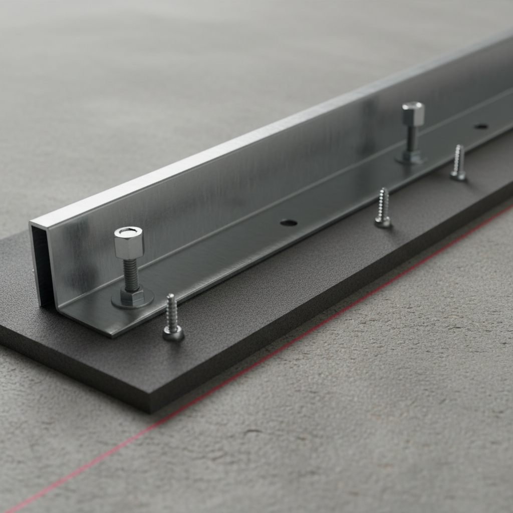
The bottom plate converts wall forces into the slab and holds layout while the top connection accommodates vertical drift. Studs seat into the track flanges, screws engage through pre-punched holes, and anchors or pins secure the web to concrete or wood substrates.
A typical assembly includes: bottom track fastened to concrete, studs inserted at layout, and a head-of-wall connection—often a slotted deflection track—to allow the structure to move independently of the partition. This separation prevents drywall cracking when the floor above moves under live loads or temperature changes.
- Track-to-slab: Use concrete screws, expansion anchors, or powder-actuated fasteners. Embedment of 1 1/4–1 1/2 inches in normal-weight concrete is common for light partitions.
- Gaskets and sealants: A foam sill gasket or acoustical sealant under the web blocks air and sound. Continuous beads at both sides of the track reduce flanking.
- Layout: Mark 16 or 24 inches on center along the top track and transfer to the slab with a plumb laser for consistent stud locations.
- Stud seating: Cut studs 1/2–3/4 inch short when using a deflection head to avoid compression during drift.
When we support jobs in mixed-metric environments, we provide both imperial and metric load tables and product brochures so site teams can coordinate layouts (for example, 400 mm approximates 15 3/4 inches). That simple alignment avoids accumulation of 1/8-inch errors across long runs.
Types, Methods, and Approaches for Bottom Plates
Choose track by function: Standard Track for most interiors, Deep Track for added flange engagement, and Slotted Deflection Track at the head to allow vertical movement. Combine with the right anchors, gaskets, and sealants to meet structural and acoustic goals.
Track profiles you’ll use
- Standard Track: Everyday non-load-bearing interiors. Matches stud width; flange height typically 1 1/4 inches for reliable screw edge distance. See our steel stud wall framing overview for system fit.
- Deep Track: Taller flanges increase stud engagement—handy for tall or high-traffic partitions.
- Slotted Deflection Track (Head-of-wall): Slots permit 1/2–1 inch of vertical drift while studs remain captive. Explore our slotted track guide and the product page for slotted deflection track details.
- U-Flex Track (curved walls): Pre-notched webs make radiused partitions quick without field kerfing.
Anchorage methods at the floor
- Concrete screws: Predictable pull-out; predrill 3/16–1/4 inch holes with dust removal for best bite.
- Expansion anchors: Good in cracked concrete; follow manufacturer’s torque and embedment (often ≥1 1/4 inches).
- Powder-actuated fasteners: Fast production in dense slabs; validate power level on a test shot and maintain spacing (e.g., 24–36 inches on center).
- Adhesive plus mechanical: In sensitive substrates, a hybrid approach can reduce required fastener counts—confirm with the specifier.
Moisture and acoustics at the base
- Sill gaskets: Closed-cell foam breaks capillary moisture and air. A 3–6 mm layer is typical under the web.
- Acoustical sealant: Continuous beads each side of the track plus resilient channel can add measurable STC improvement.
- Floor prep: Remove curing compounds or dust to keep anchors and sealants performing as designed.
Best Practices: Layout, Fastening, and Tolerances
Snap straight lines, prep the slab, dry-fit openings, then fasten track at consistent spacing. Keep straightness within 1/8 inch over 10 feet, maintain 1 inch clearance at the head for deflection, and seal both sides of the base track to control sound and air.
Layout and prep
- Use a rotary laser to project the top track line down; transfer marks every 16 or 24 inches on center.
- Vacuum dust; verify slab level within 1/4 inch over 10 feet. Feather low spots with floor patch before setting track.
- Pre-cut gaskets and stage anchors at 30–36 inches on center so crews don’t pause to search for hardware.
Fastening and spacing
- Keep first and last fasteners within 6 inches of ends; maintain 24–48 inch typical spacing in the field unless specified otherwise.
- Where water exposure is possible, use corrosion-resistant fasteners and seal penetrations with compatible sealant.
- At door openings, add fasteners 6 inches from jambs and provide solid backing for frames and hardware.
Deflection and movement
- Use slotted head-of-wall track where vertical drift is expected (often 1/2–1 inch). Cut studs 1/2–3/4 inch short.
- In seismic regions, confirm lateral bracing and anchor capacities per the project’s structural notes.
- Maintain a continuous acoustic seal at the base to prevent flanking, especially under corridor walls.
For additional system context, our team summarizes framing fundamentals in the metal studs guide and compares applications in steel studs: build smarter. Both resources help align subtrades on spacing, backing, and finish sequencing.
Tools and Resources You’ll Need
Bring a laser, chalk, sill gasket, anchors, and the right tracks. Prep with a vac and PPE, then follow a simple 10-step sequence: line, dry-fit, gasket, predrill, set, fasten, verify plumb, brace, seal, and document with photos for closeout.
- Rotary laser, chalk line, plumb bob, and steel tape (metric/imperial)
- Hammer drill with 3/16–1/4 inch masonry bits; cordless impact driver
- Powder-actuated tool (where approved) and inspection cards
- Closed-cell sill gasket, acoustical sealant, and compatible cleaners
- Concrete screws or expansion anchors with specified embedment
- Personal protective equipment: eye, ear, gloves, and dust control
- Confirm wall lines and door locations; mark 16/24 inches on center.
- Vacuum and prime dusty slab edges if sealant requires it.
- Roll the gasket, align track to the chalk, and clamp at ends.
- Predrill holes; set anchors starting 2–6 inches from ends.
- Check straightness within 1/8 inch over 10 feet; adjust as needed.
- Install studs; add blocking and rough openings.
- Install head-of-wall slotted track; cut studs short for drift.
- Brace, then apply acoustic seal both sides of the track.
- Document with photos of anchor spacing and gasket continuity.
- Release to drywall after MEP rough-in verification.
For more partition planning, see our drywall and metal studs guide which outlines sequencing and coordination tips that reduce rework during high-traffic phases.
Bottom Track Options and Use Cases
Match track to intent: Standard Track for most interiors, Deep Track for added engagement, U-Flex for curves, and Slotted Track at the head for drift. Select gauge by height and loading, and pair with anchors appropriate to the substrate and spacing.
| Track type | Typical use | Key detail | Example application |
|---|---|---|---|
| Standard Track | Non-load-bearing interiors | 1 1/4 in flange; anchors 24–48 in o.c. | Office partitions, multifamily corridors |
| Deep Track | Tall partitions, busy areas | Taller flange engages studs more | Schools, hospitals, retail backs |
| Slotted Deflection (head) | Movement/drift at top | Slots allow 1/2–1 in vertical play | Long spans under live loads |
| U-Flex | Curved walls | Pre-notched for radius | Feature walls, lobbies |
Want to deep-dive deflection head details? Our slotted track guide walks through slot orientation, screw patterns, and common inspection notes so your submittals and field photos align.
Case Studies and Field Examples
Bottom plate planning saves hours later. These quick examples show how tighter lines, right anchors, and proper gaskets prevent ripples in drywall, door binding, and noise leaks—on projects from tenant fit-outs to healthcare renovations.
- Tenant improvement, Ontario: Crew pre-staged anchors at 32 inches on center and used lasers for layout. Result: 12% faster framing across 8,000 linear feet and fewer baseboard corrections.
- Healthcare renovation, U.S. Midwest: Slotted head-of-wall track with studs cut 5/8 inch short stopped recurring joint cracks after overnight mechanical cycling.
- Multifamily corridor: Continuous sill gasket and perimeter seal added 3–5 dB to an STC 45 assembly by removing floor flanking paths.
- Curved lobby feature: U-Flex Track reduced layout time by a full shift compared to field-kerfed alternatives and delivered a smoother radius for reveals.
On slab-on-grade builds supported from Vaughan, we often recommend confirming vapor retarder integrity and keeping anchors above control joints. Pairing framing with reinforcement planning helps reduce slab movement that shows up as cracked base joints. See these concrete resources from our sister team on footing rebar details and welded wire mesh reinforcement for coordination ideas between trades.
Mistakes to Avoid (and How to Fix Them)
Don’t rush lines, skip gaskets, or mismatch anchors. Correct by re-snapping layout, replacing compromised sealant, and adding fasteners near ends and openings. Confirm drift at the head before drywall to prevent cracks and door rub.
- Wavy lines: Re-snap and reset; shim low spots rather than forcing the track.
- No gasket under web: Pull short runs and add gasket; reseal both sides to restore STC and air seal.
- Over-spaced anchors: Add intermediate fasteners to return to 24–36 inch spacing; photo-document.
- Studs cut full height with deflection head: Trim 1/2–3/4 inch and re-seat to allow movement.
- Corrosion risk: Swap to coated fasteners and seal penetrations in wet areas.

Specification Notes, Submittals, and Inspection Photos
Align specs to product data, then prove it with photos. Submit track profiles and gauges, anchor type and spacing, gasket/sealant details, and head-of-wall deflection assemblies. Field photos should show line snap, anchor spacing, and continuous seals.
- Product data: Track size, gauge, and coating; studs at 16/24 inches o.c.; head-of-wall slot capacity.
- Anchorage schedule: Anchor type, diameter, embedment, and 24–48 inch spacing or per-calculated loads.
- Acoustic details: Sill gasket spec, sealant type, and any resilient channel layout. For context, review benefits of steel in non-load-bearing walls.
- Inspection photos: Show chalk lines, end fasteners within 6 inches, and sealed perimeters before drywall.
Need a refresher on system planning before you submit? Start with our drywall framing mistakes guide to anticipate common plan/spec gaps that slow approvals.
Frequently Asked Questions
Install bottom track on a snapped line with a gasket, then fasten to the slab at consistent spacing. Use slotted head-of-wall track to allow movement, and cut studs short to avoid compression. Seal both sides of the base for better sound isolation.
What does the framing bottom plate do?
It fixes the wall layout to the floor, receives studs, and transfers forces into the slab. With a sill gasket and perimeter seal, it also helps control air and sound. Accurate track placement reduces drywall shimming and keeps door frames square.
How far apart should bottom plate anchors be?
Field spacing commonly ranges from 24 to 48 inches on center for non-load-bearing partitions, with fasteners within 6 inches of ends and at jambs. Always follow the project specification and adjust for substrate, height, and lateral bracing requirements.
Do I need a gasket under the steel track?
A sill gasket or acoustical sealant under the web is recommended in most interiors. It blocks capillary moisture, improves air sealing, and can add several decibels to STC performance by reducing flanking at the floor line.
How do I handle head-of-wall movement?
Use a slotted deflection track at the head and cut studs 1/2–3/4 inch short so the partition can move without stressing drywall. Maintain the base connection and continue acoustic seals for performance.
When should I choose Deep Track?
Deep Track is helpful on tall walls or high-traffic areas where extra flange engagement improves stud seating. It’s also a smart pick when tolerances are tight and you want more hold for reveals and specialty trims.
Next Steps and How We Can Help
Need a fast, code-aligned track package? Dass Metal Products manufactures Canadian-made Standard, Deep, Slotted, and U-Flex tracks with quick delivery across Ontario, Canada, and the U.S. Our engineers help you match gauge, spacing, and anchors to the job.
Let’s make your next layout the straightest on site. Our team in Vaughan supports contractors and distributors with brochures, load tables, and takeoff assistance so your framing bottom plate goes down right the first time.
- Explore slotted head-of-wall options on the slotted deflection track page.
- Review system basics in the metal studs guide and steel stud wall framing overview.
- Coordinate with concrete teams using welded wire mesh tips for flatter slabs and cleaner base details.
Key Takeaways
- The framing bottom plate (steel track) locks layout and transfers loads.
- Straight lines, right anchors, and continuous seals prevent finish problems.
- Use slotted track at the head to handle 1/2–1 inch vertical movement.
- Gaskets and resilient details help partitions reach STC 45–50.
- Stage materials and document spacing to speed inspections and closeout.
Ready for submittal-ready details? Request Dass Metal product data and load tables so your bottom plate package installs fast and passes inspection the first time.