Shaft wall framing is a specialized wall system used to enclose elevator, mechanical, and utility shafts with fire- and smoke-rated assemblies. It relies on C-H studs, J-tracks, and 1-inch shaftliner panels to create a robust barrier. For teams in 370 New Enterprise Way and across Ontario, it streamlines schedules and reduces rework when detailed correctly.
By Navjot Dass — Dass Metal Products
Last updated: 2026-05-23
Summary
This guide explains what shaft wall framing is, why it matters, how it works, and how to install it correctly. You’ll learn assembly components, step-by-step methods, best practices, tools, and real project examples tailored to elevator and mechanical shafts.
Here’s what you’ll learn in this 2026 field-ready guide, created for builders, GCs, drywall and framing contractors, and specifiers working with steel studs and shaftliner systems.
- Clear definitions and code-aligned uses for shaft wall systems
- Core components: C-H studs, J-tracks, slotted deflection heads, 1-inch liners
- Installation workflow that reduces punch-list items
- Acoustic, fire, and movement considerations for durable performance
- Common errors to avoid and quality control checkpoints
- Procurement and scheduling tips for tight timelines
For background on studs and tracks, see our steel stud wall framing basics and our overview of slotted deflection track best practices.
What Is Shaft Wall Framing?
Shaft wall framing is a light-gauge steel assembly that holds 1-inch gypsum shaftliner panels between C-H studs and J-tracks to create a rated barrier around elevator, mechanical, and utility shafts. It’s engineered for fire, smoke, and acoustic control while allowing construction from one side of the wall.
In our experience supporting projects throughout Canada and the United States, the most reliable assemblies share four traits: correct materials, precise layout, disciplined sequencing, and documentation. Get those right and you’ll see fewer RFIs, cleaner inspections, and faster closeout.
- Typical rating: Many shaft wall designs are listed for 2-hour fire resistance when built with specified components and details.
- Panel standard: 1-inch (approx. 25 mm) shaftliner gypsum is the core element; it slides into C-H studs captured by J-tracks.
- Stud spacing: 24 inches o.c. is common; 16 inches o.c. is used where higher impact or load is expected—follow the design and listings.
- Movement: Deflection heads accommodate vertical building drift—clearances are often 1/2 to 1-1/2 inches, per spec.
To select the right profile set, review your submittal with a focus on stud gauge (20–14 ga), liner type, and head-of-wall movement criteria before material release.
Why Shaft Walls Matter
Shaft walls protect egress, equipment, and occupied spaces from fire, smoke, and noise while enabling one-sided installation in tight cores. They improve safety, speed inspections, and standardize quality across multi-story construction when paired with engineered steel studs and listed details.
Elevator and mechanical cores are the heartbeat of mid-rise and high-rise projects. A single layout error can ripple across 10–30 floors. We’ve seen schedules slip days per floor when head-of-wall movement joints aren’t coordinated—small misses scale fast in vertical work.
- Life safety: Rated assemblies limit fire and smoke spread along vertical shafts—the most vulnerable pathways in a building.
- One-sided build: Crews can frame from corridors or lobbies, avoiding exposure to open shafts and reducing fall risks.
- Inspection clarity: Using listed, documented systems speeds approvals and reduces back-and-forth with AHJs.
- Acoustics: Properly detailed walls with resilient channel and insulation can cut perceived noise by noticeable margins in occupied floors.
When you combine rated liners with engineered CH shaftwall studs and purpose-made tracks, you get predictable stiffness, easier handling, and fewer field modifications.
How Shaft Wall Systems Work
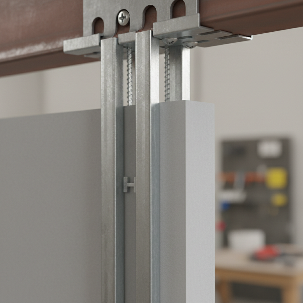
A shaft wall uses bottom and top J-tracks to capture C-H studs. Installers slide 1-inch shaftliner panels vertically between studs from the accessible side, then add face layers of gypsum as required. A slotted deflection track at the head allows the structure to move independently.
Think of the assembly as a cartridge system: the tracks create a channel, the C-H studs provide capture points, and the liner panels lock everything in. The face layer(s) on the corridor side finish the wall, meet the required rating, and deliver the final surface for taping and paint.
- Layout: Snap lines, confirm openings, set control joint locations, and mark penetrations and anchors. Verify clear shaft dimensions against drawings.
- Track install: Place J-track at the base; use a slotted deflection track at the head per deflection requirement.
- Studs: Insert C-H studs at specified spacing (commonly 24 inches o.c.; tighten to 16 inches where noted).
- Liners: Slide 1-inch panels from floor to head, engaging the stud flanges; stagger joints as detailed.
- Face layer(s): Add gypsum board on the occupied side, fastening to studs per pattern; finish joints.
- Seal: Apply fire/smoke sealants and acoustical sealant at perimeters and penetrations as specified.
| Step | What to Verify | Common Tolerance |
|---|---|---|
| Head-of-wall | Slot length and clearance | ~1/2–1-1/2 in. movement |
| Stud spacing | O.C. vs. design loads | 16 or 24 inches o.c. |
| Panel joints | Stagger and fit | Factory edge alignment |
| Fasteners | Type and pattern | Per listing/spec |
For a deeper primer on studs and layout workflows, review our steel stud framing guide.
Types, Methods, and Approaches
Most shaft walls rely on C-H studs, bottom J-track, and top slotted track with 1-inch shaftliner panels. Variations include double-stud corners, impact-resistant corridors, added resilient channels for acoustics, and special profiles for curved or offset cores.
Core components you’ll specify
- C-H (CH) shaftwall studs: Purpose-formed profiles that capture 1-inch liners; gauges often range from 20 to 14, per design.
- J-track: Base and intermediate capture; easy drop-in for liners.
- Slotted deflection track: Head-of-wall movement; match slot length to structural drift.
- 1-inch shaftliner gypsum: Inserted from the accessible side; provides core fire resistance.
- Face layers: One or two layers on the occupied side to meet rating and finish requirements.
Assembly variations and when to use them
- High-traffic corridors: Tighten stud spacing to 16 inches o.c. and use abuse-resistant face board.
- Acoustic zones: Add resilient channel and insulation; an additional face layer can improve perceived noise reduction.
- Curved cores: Use segmented J-track or request a U-Flex track-style solution; plan more, cut less.
- Service-intensive shafts: Coordinate access panels and sleeve clusters early; group penetrations to limit cutouts.
- Tall walls: Verify stud gauge and bridging needs; introduce bridging/carrying channel if required by engineering.
If your core requires special geometry, our team can produce special profiles that reduce field cutting and speed layout. That’s often the fastest way to control variance across multiple floors.
Best Practices That Prevent Rework
Use listed details, confirm deflection requirements, and pre-coordinate penetrations. Tighten stud spacing where impacts are expected, stage materials floor-by-floor, and document each inspection point. These habits cut rework and punch items on multistory cores.
Preconstruction checkpoints
- Coordinate head-of-wall deflection with structural and envelope teams; choose a slotted track that meets the actual drift.
- Schedule material release per floor; stage 1-inch liners near each bay to avoid double-handling.
- Confirm rated door frames, dampers, and sleeves so wall openings align with hardware.
Field execution tips
- Snap lines and use laser layout to keep studs plumb—variance compounds over 10–30 floors.
- Fasten per pattern; over-fastening can telegraph through finishes and waste time.
- Seal perimeters with approved fire/smoke sealants; acoustical sealant where sound control is required.
Quality and safety notes
- Document each step with photos tied to floor numbers; inspectors appreciate clarity and consistency.
- Leverage one-sided installation to minimize exposure to open shafts and reduce edge protection needs.
- Where impacts are frequent, 16 inches o.c. stud spacing and denser board reduce dent repair cycles.
For more execution guardrails, see our guide to avoiding common interior framing mistakes.
Tools and Resources
Plan with a submittal package that includes product data, load tables, listings, and head-of-wall details. Use checklists for layout, fastener selection, and inspections. Align procurement and staging to floor-by-floor work sequencing.
Specification and submittal
- Current product data for CH studs, J-tracks, and slotted tracks
- Listings and UL/Intertek report numbers for the required rating
- Movement joint details with slot lengths and sealant types
- Load tables and span charts for selected gauges
Field checklist (printable)
- Lines snapped, openings marked, penetrations coordinated
- Head slot length verified against structural drift
- Stud spacing confirmed (16 or 24 inches o.c.)
- Fastener type/pattern per listing; no overdriving
- Perimeter/fire/smoke seals installed and documented
New to metal studs? Start with our metal studs guide and the broader steel framing systems overview for context.
Acoustics, Fire, and Movement Performance
A compliant shaft wall balances fire rating, acoustic separation, and structural movement. Combine 1-inch liners with the right stud gauge, seal continuous perimeters, and use resilient channels or insulation where noise control is critical.
Noise climbs quickly through vertical chases. Even simple steps—insulation plus resilient channel on the occupied side—can change customer satisfaction on multi-tenant floors. Similarly, head-of-wall deflection that actually matches structural drift prevents board cracking during seasonal movement.
- Fire: Maintain continuous liner coverage and listed joint treatments; face layers must meet the specific listing.
- Acoustics: Resilient channel and batt insulation on the occupied side can significantly reduce perceived transmission.
- Movement: Select slot length based on expected vertical drift; document clearance before cover-up.
When in doubt, align selection with your listed assembly and verify details against submittals before closing walls.
Pricing and Procurement Factors (No Numbers)
Control total installed value by aligning gauge to loads, spacing to impacts, and head-of-wall solutions to real drift. Release materials in phases, reduce cuts with special profiles, and coordinate penetrations to avoid late-stage rework.
While we don’t discuss pricing, the drivers are predictable: material gauge, stud spacing, deflection head complexity, and field labor hours tied to layout and cuts. A clean submittal plus accurate takeoff lowers surprises later. For estimating context and scope organization, see our discussion of how metal stud framing is estimated.
- Confirm floor-by-floor release dates and elevator access timing.
- Use special profiles to minimize cuts around offsets and stairs.
- Order additional liners for inevitable damage and penetrations.
- Bundle face-layer boards per floor to avoid double-handling.
Case Studies and Field Examples
Consistent results come from disciplined layout, matched components, and documented inspections. The mini case insights below show how minor adjustments—like track selection or stud spacing—remove hours of rework per floor across multi-story cores.
Elevator core with misaligned head slots
A contractor reported board cracking at several floors. The root cause was under-sized head slots relative to measured drift. Switching to a longer slotted deflection track eliminated the issue on subsequent levels.
Mechanical shaft with dense penetrations
Grouping sleeves into “clusters” reduced individual cutouts by over a dozen per floor and simplified inspection sign-offs. A stud spacing change from 24 inches to 16 inches o.c. near equipment pads improved impact resistance.
Curved stair core
Segmented J-tracks were time-consuming to cut. A switch to a special-profile curved track (U-Flex style) cut installation time and produced smoother board finishes at the inside radius.
Mixed-use tower acoustics
Tenant complaints dropped after adding resilient channel and insulation to corridor faces adjacent to elevator runs. The team documented before/after sound readings at consistent times to validate the improvement.
Fast-track renovation
Material staging at two floors ahead kept crews productive during elevator outages. The superintendent’s daily log tied photos to floor numbers, expediting AHJ approvals.
One-sided safety gains
Leveraging one-sided installation reduced edge protection demands along the shaft opening. Crews maintained clip-on lanyards at loading points while staying off the unprotected side.
Large-format openings
Coordinated rated doors and access panels at submittal prevented mid-install changes. The PM onboarded suppliers early to verify lead times before framing began.
Impact corridor retrofit
Switching to abuse-resistant face board at lower 4 feet and tightening to 16 inches o.c. below handrail height reduced recurring dent repairs by week two.
Offset shaft
Where the shaft jogged by a few inches, a special-profile track eliminated field shims and cut alignment time noticeably. Less shim stock also meant cleaner firestopping.
Cold-weather logistics
Staging 1-inch liners on skids per floor avoided moisture exposure and damage during winter handling. Daily counts prevented shortages during weekend pushes.
Training new crews
Foremen used a one-page checklist at starts-of-shift. Fewer than five misses per floor were recorded after week one, down from double-digits.
Spec alignment
When the crew cross-checked fastener patterns against the listing, two areas were corrected early, preventing rework later. Photography at each stage improved transparency with the owner’s rep.
Explore component options in our shaftwall CH stud product page and related steel framing safety overview.
Local Tips: Working in 370 New Enterprise Way
Plan shaft wall work around elevator access windows, winter handling, and local inspection rhythms. Stage liners per floor, protect materials from moisture, and document head-of-wall clearances to streamline approvals in the regional construction environment.
Local considerations for 370 New Enterprise Way
- Schedule floor-by-floor releases to align with elevator access windows commonly seen in busy metro cores; it reduces idle time and double-handling.
- Cold-season handling matters: keep 1-inch liners dry and acclimated to minimize edge damage and board movement before finishing.
- Inspection cadence: pre-stage submittals and head-of-wall photos; clear, repeatable documentation speeds approval cycles in the region.
Step-by-Step Installation (Field Sequence)
Snap layout, install base J-track and slotted head track, set C-H studs to spacing, slide 1-inch liners, add face layers, and seal perimeters. Document each stage with photos and checklists to simplify inspections and closeout.
- Verify shaft dimensions, mark openings, and identify penetrations.
- Install base J-track and head slotted track; confirm slot length vs. drift.
- Set C-H studs at 24 inches o.c. (or 16 inches where required).
- Slide 1-inch shaftliner panels from the corridor side; stagger joints.
- Add corridor face layer(s) per listing; fasten per pattern.
- Seal perimeters and penetrations; label rated access panels.
- Photo-document head clearance and fastener patterns; file daily.
On projects mixing structural and interior schedules, coordinate head-of-wall deflection details during MEP coordination week—it prevents late redesigns.

Shaft Wall vs. Alternatives
Compared to CMU or conventional stud-and-board partitions, shaft walls offer listed fire performance, one-sided build, and lighter dead load. They’re ideal in tight cores and multi-story work where speed and safe access matter.
| System | Access | Fire/Smoke | Weight | Speed | Best Use |
|---|---|---|---|---|---|
| Shaft wall (CH/J) | One-sided | Listed assemblies | Light | Fast | Elevator/mech cores |
| CMU | Two-sided | Inherent mass | Heavy | Slower | High abuse zones |
| Conventional stud + board | Two-sided | Varies by layers | Light | Moderate | Non-shaft partitions |
For load-bearing needs outside shafts, compare with our heavy-gauge framing system overview.
Need a Second Pair of Eyes?
Send us your shaft wall detail set for a quick constructability review. We’ll flag gauge mismatches, head-of-wall gaps, and procurement risks so you can build faster with fewer RFIs.
Our engineering team has more than 40 years in steel framing. Share a markup and we’ll respond with practical, field-ready notes—so your crew shows up with the right studs, tracks, and liner counts the first time.
Frequently Asked Questions
These concise answers address the most common shaft wall framing questions from builders, contractors, and specifiers. Use them to align teams before mobilization.
What is the standard thickness for shaftliner panels?
Most listed shaft wall systems use 1-inch gypsum shaftliner panels as the core element. Always verify the exact product and any face-layer requirements in your project’s approved submittals and listings before ordering materials.
Can I build a shaft wall from one side only?
Yes. Shaft wall assemblies are designed for one-sided installation. Installers place C-H studs and tracks from the accessible side and slide 1-inch liners vertically into position, then add face layers on the corridor side as required.
How do I allow for building movement at the head of wall?
Use a slotted deflection track sized to the expected vertical drift and maintain the required clearance. Photograph the slot and clearance before cover-up to document compliance for inspections and closeout.
What stud spacing should I use in high-traffic corridors?
Where impacts are expected, 16 inches on center is a common choice to improve stiffness and reduce dents. In standard conditions, designs often use 24 inches on center. Follow the approved drawings and listed assembly requirements.
Do I need resilient channel for acoustic control?
Not always, but it helps. In mixed-use or residential floors adjacent to elevator runs, resilient channel combined with insulation on the occupied side can noticeably reduce perceived noise transmission.
Key Takeaways
Pick listed components, match slot length to drift, tighten spacing where needed, and document each step. This combination delivers repeatable, inspection-ready shaft walls across multi-story projects.
- Use CH studs, J-tracks, and 1-inch liners matched to a listed assembly.
- Size slotted tracks to real structural movement—then verify in photos.
- Stage materials floor-by-floor; protect liners from moisture.
- Tighten spacing to 16 inches o.c. in impact zones; use abuse-resistant board.
- Seal perimeters and penetrations; keep a simple field checklist.
Related Topics in Framing
Explore adjacent steel framing topics to round out your team’s playbook—stud selection, deflection heads, and system planning that prevents delays and rework.
Build broader context with our primers on steel stud wall framing, deflection track selection, and high-level steel framing safety. For takeoffs and scope alignment, see field-tested framing workflows.