load bearing stud framing: selection, detailing, and site checkpoints
What is load bearing stud framing?
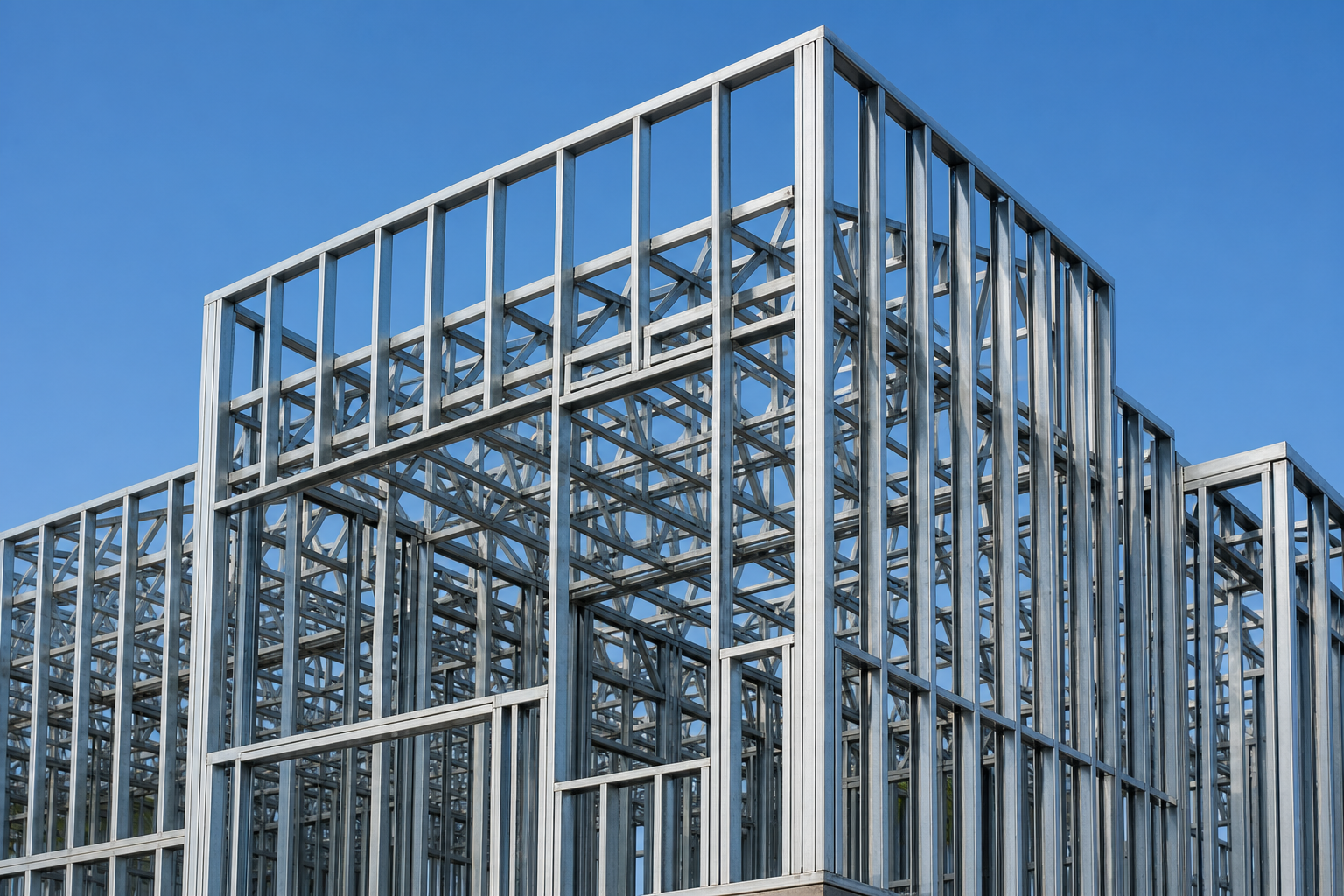
Unlike non-load-bearing partitions, load-bearing assemblies transfer gravity and, often, lateral loads (wind or seismic, as applicable) to the structure. They typically use heavy-gauge, cold-formed steel studs set in steel tracks. The system may include bridging/carrying channels, bracing straps or windbrace, hold-downs, and connectors at floors, roofs, or transfer elements. Detailing must address:
- Axial capacity of studs and the effect of unbraced length
- Track selection and seat depth sufficient for installation tolerances
- Bridging and restraint to prevent stud buckling
- Connections that respect deflection and differential movement where required
- Openings, headers, and load paths around door/window penetrations
Choosing studs and tracks
Member selection starts with the loads and geometry shown on the structural drawings. When you review or prepare submittals, confirm the following items before fabrication or purchase:
- Stud depth, thickness (gauge), and yield strength: Verify against the design schedule. Heavier gauges and higher yield strengths increase axial and bending capacity but have implications for fastener type and installation effort.
- Unbraced length and bridging spacing: Axial capacities depend on lateral support intervals. Plan the bridging pattern during takeoff to ensure you carry enough bridging channel, clips, and fasteners.
- Track type and depth:
- Standard track is typical where little vertical movement is expected.
- Deep track can simplify stud engagement and facilitate tolerances for load-bearing lines or panelization.
- Where the top of wall must accommodate vertical movement from structure above, coordinate a deflection detail. For non-load-bearing tops, a slotted deflection track is common; for load-bearing conditions, movement is handled differently—usually by detailing the bearing connection at a floor or transfer member and separating laterally braced but vertically free elements elsewhere per design.
- Corrosion considerations: Select coating levels consistent with the project environment and specifications.
- Compatibility with finishes: Confirm flange widths suit sheathing and drywall fastening patterns.
Tip: Keep the stud and track families consistent across adjacent walls to simplify procurement and reduce change-order risk. If the design mixes interior and exterior lines, clearly differentiate member tags on shop drawings.
Detailing connections and bracing
Connections and restraint determine whether the calculated capacities are realized in the field. Pay special attention to:
- Base and top connections: Confirm fastener quantity, pattern, and edge distances. For axial-bearing lines, ensure the track and supporting structure can transfer the compressive load without local crippling as detailed in the design.
- Bridging/carrying channel and bridging clips: Bridging channel restrains stud flanges and reduces unbraced length. Place rows at the design spacing and tie back to the structure as detailed. Use compatible clips and fasteners.
- Straps and windbrace: Bracing straps or windbrace elements establish the in-plane stiffness of stud lines and shear walls where specified. Keep laps, tensioning, and anchor details consistent with the drawings.
- Connections at diaphragms and collectors: Where walls engage roof or floor diaphragms, follow specified connectors and slip details to balance lateral transfer with vertical movement requirements.
Restraint layout should be coordinated with MEP penetrations to avoid cutting bridging after installation. If a clash is unavoidable, document an alternate restraint path before proceeding.
Openings, deflection, and differential movement
Openings interrupt load paths and are a frequent source of field fixes. Reduce risk with the following steps:
- Dimension openings from control lines: Verify door and window rough openings against the finish schedule and any frame submittals.
- Header and jamb design: Use the member sizes, built-up stud counts, and connectors shown on the structural details. Keep splice locations and back-to-back orientations as specified.
- Load transfer around openings: Confirm that load from truncated studs bears into headers and jambs through clips or direct bearing, per detail.
- Deflection and movement: Where the structure above experiences vertical deflection, clarify whether the wall is intended to carry load or to slip. For non-bearing tops adjacent to load-bearing segments, a slotted deflection track or deflection clips can allow vertical movement while maintaining lateral support, as shown in project details.
Document any field changes to opening size or location early; a small shift can force a header redesign.
Installation sequence and QC
A disciplined sequence keeps tolerances tight and preserves capacity:
- Layout: Snap lines, mark stud spacing, and set control elevations. Verify slab levelness where bearing is intended. Shim only as permitted by the design.
- Track installation: Fasten base track to the supporting structure per the specified pattern. For deep track, check squareness and true alignment before placing studs.
- Stud placement and temporary restraint: Plumb each stud and tack to maintain spacing. Use temporary blocks if bridging is not yet in.
- Bridging and bracing: Install the first row of bridging low to stabilize, then proceed up the wall. Tension straps or windbrace per detail and sequence requirements.
- Permanent connections: Complete fastener patterns at bases, tops, headers, and jambs only after alignment checks.
- Sheathing and finishes: Attach sheathing and interior finishes in accordance with spacing and edge-distance requirements. Where resilient channel is specified for acoustics, map stud locations so fasteners do not short-circuit isolation paths.
- Final QC: Verify plumb, line, stud fastener counts, bridging spacing, and hold-down/collector hardware installation. Photograph concealed conditions before cover-up.
Maintain a running punch list per elevation. Early, frequent checks catch small deviations before they cascade into header misalignment or finish conflicts.
Coordination and submittals
Strong coordination reduces RFIs and preserves schedule float. Include the following in your submittal package and pre-installation meeting:
- Product data: Stud and track profiles, thicknesses, yield strengths, and coating information.
- Load tables and span data: Show that selected members satisfy axial, bending, and combined demands at the specified unbraced lengths and bridging spacing.
- Connection details: Fastener types, patterns, and any proprietary clip submittals for deflection, bridging, or anchorage.
- Shop drawings: Plan, elevation, and section cuts with member tags, opening framing, and bracing layouts. Clearly flag any deviations requested.
- Installation procedures: Sequencing notes, field tolerances, and inspection hold points.
Hold a page-turn with the structural engineer, general contractor, and affected trades to walk through movement joints, opening elevations, and restraint lines. Record decisions and update drawings promptly.
Common pitfalls and preventions
- Insufficient stud restraint: Missing or widely spaced bridging can slash axial capacity. Prevention: Pre-calc bridging counts and include clips in the takeoff; inspect spacing each lift.
- Overlooking movement at tops: Treating a slip condition as fixed can cause cracking or stud distress. Prevention: Use specified slotted components or deflection clips where detailed; label them distinctly on drawings.
- Header load path gaps: Unsupported cripple loads at openings lead to serviceability issues. Prevention: Confirm clips and bearing seats at each truncated stud.
- Mismatched fasteners: Using non-compatible screws or patterns undermines connection capacity. Prevention: Match fastener specs to member thickness and coating; mock up first-of-kind connections.
- Unplanned penetrations: Field cuts through flanges or webs can invalidate design assumptions. Prevention: Route services through predefined zones; if unavoidable, seek engineer direction before cutting.
Field checklist (one page)
Use this concise list during layout and closeout walks. Check items that apply; note N/A where not applicable.
- Stud schedule matches drawings (depth, gauge, yield strength)
- Track type and seat depth per detail; anchors at required spacing
- Stud spacing and layout verified; plumb and line within tolerance
- Bridging channel rows installed at scheduled intervals; clips fastened
- Straps/windbrace installed, tensioned, and anchored as detailed
- Openings framed with correct header and jamb members; bearing clips installed
- Top-of-wall condition (fixed, slip, or bearing) matches design intent
- Collectors/hold-downs installed, torqued, and documented
- Fastener types and counts verified at bases, tops, and connections
- Sheathing/finish attachment patterns observed; resilient channel isolated where specified
- Penetrations coordinated; no unapproved web or flange cuts
- Photo record of concealed work completed prior to cover-up
FAQ: load bearing stud framing
How do I decide between standard and deep track for bearing lines?
Deep track provides additional seat depth that can simplify installation tolerances, especially for taller studs or panelized segments. Standard track is common where tolerances are tight and movement is limited. Follow the project details; if tolerances or field conditions suggest additional seat depth is prudent, request written approval before changing.
What is the role of bridging channel in a load-bearing stud wall?
Bridging channel restrains stud flanges, reducing unbraced length and helping studs achieve their calculated axial capacity. It also improves in-plane stability during construction. Install the number of rows and spacing shown on the drawings and connect with compatible bridging clips and fasteners.
When is a slotted deflection track appropriate?
Slotted deflection tracks are typically used at the top of non-load-bearing walls to allow the structure above to move vertically without imparting unintended loads to the wall. Load-bearing conditions are handled per the structural details, which may fix or bear at specific locations while allowing slip elsewhere for differential movement. Always follow the project’s defined top-of-wall detail.
Do resilient channels belong in load-bearing assemblies?
Resilient channel is an acoustic component that decouples finishes from framing to reduce sound transmission. If specified in a load-bearing wall, coordinate its placement carefully so that fasteners do not bypass the channel and short-circuit the acoustic path. Confirm with the design team before deviating.
Can I field-cut studs around new openings without redesign?
Cutting load-bearing studs or altering flange/web geometry changes capacity and is not a like-for-like swap. Do not modify load-bearing members without written direction from the design professional of record.
Important limitation: This article provides general information about load bearing stud framing and is not a substitute for the contract documents or professional engineering. For project-specific design, connection details, and approvals, consult a qualified structural engineer or the design professional of record.