Non load bearing steel studs: selection, spacing, and detailing essentials
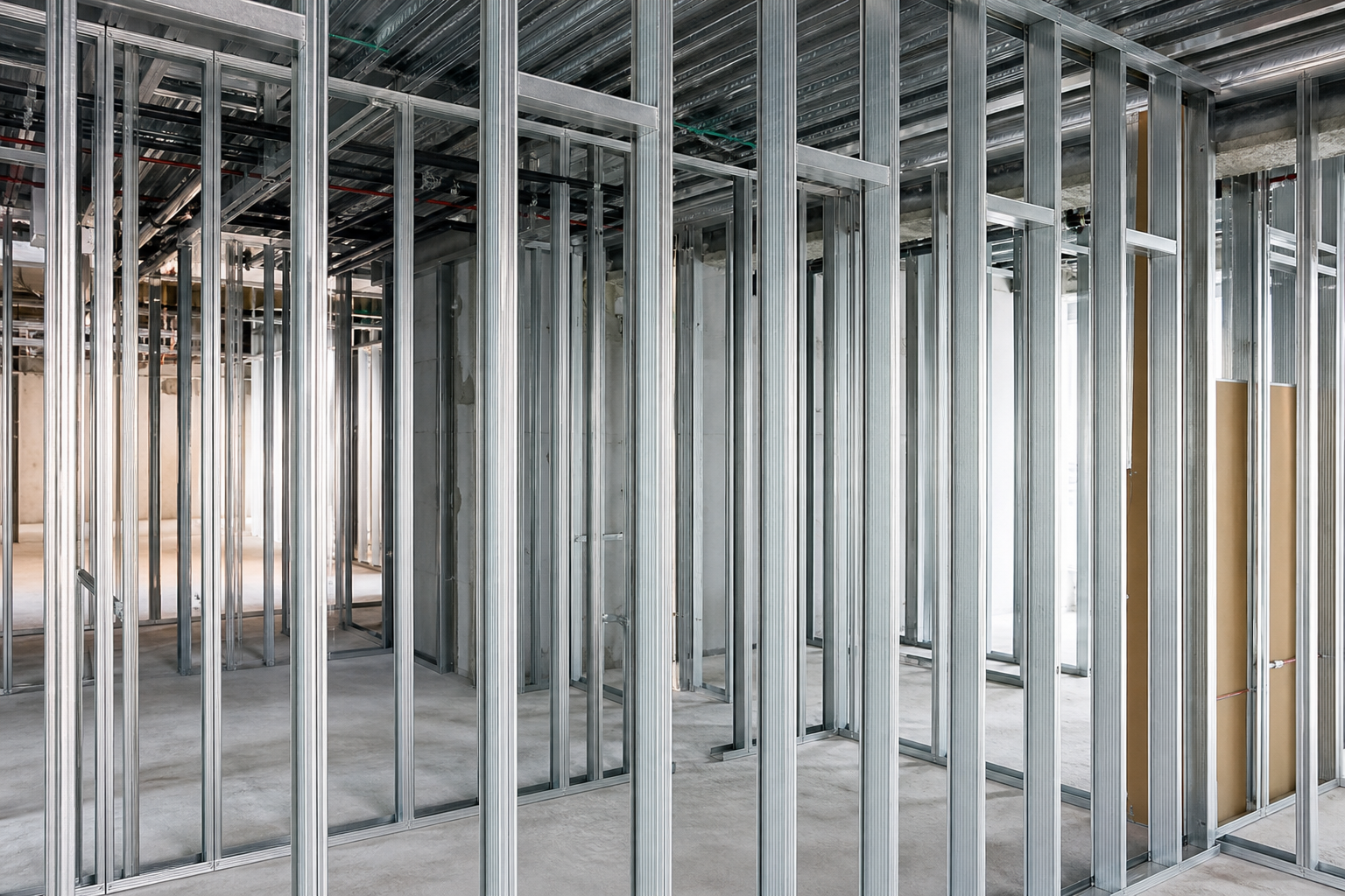
Non load bearing steel studs are the backbone of modern interior partitions and many exterior veneer backups. They do not support primary building loads like floors or roofs; instead, they carry the weight of finishes (such as gypsum board), fixtures, and their own self-weight while transferring incidental forces to the surrounding structure. Because they are cold-formed, lightweight, dimensionally consistent, and easy to coordinate with building services, these studs are the default choice for commercial interiors and increasingly common in residential and institutional projects.
What “non load bearing” means
Understanding the term sets the stage for correct specification and installation:
- No primary structural duty: Non load bearing studs are not intended to support floors, roofs, or other gravity or lateral elements of the building’s main structure.
- Partition and cladding support: They carry finishes, doors, glazing, casework, and specialty wall systems. They may also serve as backup framing for exterior veneers where the primary structure is elsewhere.
- Movement compatibility: Because the primary structure moves (deflection, thermal expansion, creep), non load bearing studs are typically detailed with allowance at the head to avoid unintended load transfer.
While the studs themselves are “nonstructural” in the global sense, they still require proper selection and detailing to meet serviceability needs like stiffness, deflection limits for finishes, and durability.
Common applications
Non load bearing steel studs appear in settings ranging from tenant fit-outs to healthcare and education. Typical uses include:
- Interior drywall partitions of various heights
- Soffits, bulkheads, and ceiling drops
- Shaft walls and corridor walls using system-specific components
- Backer framing for tile, panelized systems, or acoustic treatments
- Nonstructural exterior backup for cladding where loads bypass to structure
They integrate cleanly with tracks, channels, clips, and finishing trims to create straight, plumb, and ready-to-finish wall assemblies.
Core components and terminology
A quick vocabulary review helps align drawings, submittals, and field work:
- Stud: The vertical member (typically C-shaped) installed at regular spacing to form the wall’s frame.
- Track: U-shaped member at the top and bottom that receives the studs.
- Deflection head track: A track or clip detail at the top that allows vertical movement of the structure above without loading the wall.
- Bridging/carrying channel: Horizontal members that restrain stud twist and help distribute incidental loads.
- Resilient channel/furring: Secondary members to decouple or true the finish layer, often for acoustics or alignment.
- Clips and accessories: Connectors for deflection, alignment, or lateral restraint, sized to the stud depth and function.
Selection criteria
Choosing the right non load bearing steel studs is about matching performance to project needs while keeping the assembly efficient and buildable. Consider the following:
- Stud depth: Common nominal depths provide cavity space for services and insulation. Taller partitions often require deeper studs for stiffness and service routing.
- Gauge/thickness: Thinner light-gauge options suit short, lightly loaded partitions; heavier light-gauge options help control deflection at taller heights or where heavy finishes and fixtures are present.
- Spacing: 16 in. and 24 in. on-center are typical baselines; spacing tightens for heavy finishes, tall walls, or where stiffness targets are tight.
- Deflection limits: Establish allowable out-of-plane deflection for the finish system and pick stud size/gauge and spacing to meet that serviceability target.
- Corrosion exposure: Select appropriate coatings for humid interiors, intermittent moisture, or near-exterior conditions to maintain durability.
- Acoustic goals: Where sound isolation matters, plan for resilient channels, insulation, and sealants—then check how these affect stud spacing and detailing.
- Openings and loads: Doors, sidelites, and wall-mounted equipment often govern local stud sizes, king/jamb reinforcement, and cripple arrangements.
Always confirm selections against the project’s drawings and submittal requirements. Manufacturer literature and load/deflection tables are commonly used to verify height, spacing, and gauge combinations for targeted performance.
Spacing and layout
Layout affects both performance and build speed:
- Standard spacing: 16 in. o.c. typically offers increased stiffness and better support for heavy finishes; 24 in. o.c. can be appropriate for lighter finishes and shorter heights.
- Consistent module: Keep a consistent on-center module to coordinate with panel widths and MEP penetrations. Align studs at control joints, corners, and termination points.
- Edge and corner studs: Double up where finishes change direction or where accessories (beads, trims) need firm backing.
- Service penetrations: Pre-plan openings for plumbing/electrical to minimize cutouts and maintain stud capacity. Use manufacturer-specified punchouts where provided.
Head and base details
Correct head and base conditions protect finishes and avoid unintended load sharing with the structure:
- Base track: Anchor the bottom track per project documents. Maintain continuous sealant where required for acoustics or separation.
- Standard head track: Where the structure above is not expected to deflect into the partition, studs can be tight to a fixed top track per drawings.
- Deflection head track: For typical structures with live-load deflection, slot or slip connections at the head allow the structure to move without loading the studs or crushing finishes. Observe required gaps and do not fasten the stud web to the deflection slot where slip is intended.
- Tolerance and plumb: Verify plumbness after anchoring tracks; minor misalignment compounds across the wall and affects finish quality.
Openings, doors, and glazing
Openings localize forces and need deliberate reinforcement:
- Jambs and kings: Heavier-gauge studs or doubled members are typical at door jambs; confirm sizes and reinforcement details.
- Headers: Even in non load bearing walls, local headers support finishes and transfer incidental loads to jambs. Match header profiles and fastener patterns to the span and weight above.
- Anchorage: Coordinate frame anchors, glazing channels, and hardware with stud positions to avoid field conflicts.
- Finish transitions: At sidelites and glazing pockets, maintain continuous backing for sealants and trims.
Bracing, bridging, and lateral restraint
Non load bearing steel studs benefit from intermediate restraint to prevent twist and control lateral movement:
- Bridging/carrying channel: Install at intervals per submittals to restrain stud flanges. More frequent bridging can reduce stud wobble and improve finish flatness.
- Clip connections: Use appropriate clips to tie studs to bridging or structure without defeating required deflection allowances.
- Soffits and returns: Short legs and irregular geometries often need additional lateral ties to maintain line and level.
Acoustics, fire, and envelope considerations
Partitions often do double duty: divide space, block sound, and meet life-safety and enclosure goals. Keep these in mind:
- Acoustics: Resilient channels, insulation, and careful perimeter sealing typically improve sound isolation. Avoid hard bridges that short-circuit acoustic designs.
- Fire and smoke: Where rated or smoke-resistant assemblies are required, follow the tested assembly’s details for stud size, board type, layer count, and joint treatments.
- Envelope adjacency: At exterior-adjacent partitions, coordinate vapor control layers, thermal breaks, and corrosion protection for components exposed to moisture or temperature swings.
The governing project specifications and drawings define the required ratings and acoustic targets; the stud selection should support, not drive, those outcomes.
Fasteners and accessories
Performance depends on the fasteners holding the system together:
- Stud-to-track attachment: Follow specified screw types and patterns. At deflection heads, fasten only where permitted to preserve slip capacity.
- Bridging connections: Use the clip or screw configuration called out in submittals to ensure lateral restraint performs as intended.
- Finish attachment: Drywall screw type and spacing affect finish performance, especially at edges and around openings.
- Corrosion-resistant options: In humid zones or near exterior transitions, use coated fasteners compatible with the stud’s protective finish.
Coordination with other trades
Early coordination prevents rework:
- MEP routing: Confirm stud punchout locations and sizes align with conduit and piping runs. Oversized field cuts can compromise stud performance.
- Ceilings and floors: Align track locations with ceiling grid perimeters and floor transitions to avoid awkward reveals or trim build-ups.
- Door and millwork teams: Verify blocking, backing, and reinforcement for hardware, casework, and specialty equipment before closing walls.
Installation best practices
Reliable results come from a repeatable process:
- Verify layout: Snap clear, dimensionally checked lines for tracks. Confirm door and opening locations before anchoring.
- Anchor tracks: Install bottom and top tracks straight and level; use anchors suited to the substrate.
- Stand studs: Insert studs into tracks, crown facing the same way, and fasten per pattern. Keep webs aligned for a flat plane.
- Add bridging: Install required lateral restraint at specified heights and intervals.
- Complete head details: Where slip is required, maintain the design gap and avoid pinning the stud to the structure.
- Check plumb and plane: Before boarding, sight walls for kinks or bows; adjust bridging and fasteners as needed.
- Close with finishes: Hang boards per pattern, treat joints, and install trims and beads with continuous backing.
Quality control and troubleshooting
Spot issues early to save time and cost:
- Oil-canning or flutter: Add or reposition bridging; verify stud gauge and spacing meet deflection targets.
- Cracked joints: Check for over-deflection, missing perimeter sealant in acoustic assemblies, or rigid head connections where slip was required.
- Door frame racking: Confirm jamb reinforcement, proper shims, and plumbness; ensure headers transfer loads cleanly to jambs.
- Corrosion spots: Identify moisture sources, ensure protective coatings are intact, and replace compromised members.
Checklist before you specify
- Wall height, finish weight, and serviceability deflection limit identified
- Stud depth, gauge, and spacing selected to meet targets
- Deflection head requirement and gap dimension confirmed
- Door, glazing, and equipment loads coordinated with reinforcement details
- Bridging intervals and clip types defined
- Acoustic, fire, and envelope details coordinated with the partition type
- Corrosion protection level and compatible fasteners specified
- MEP penetrations aligned with stud punchouts or framed openings
- Finishing trims, beads, and control joints planned
- Submittals to include product data and applicable load/deflection information
FAQs about non load bearing steel studs
What’s the difference between non load bearing and load-bearing studs?
Non load bearing studs frame partitions and support finishes but are not intended to carry primary building loads. Load-bearing studs are heavier-gauge members designed and detailed to transfer structural loads such as floors and roofs to the foundation or primary structure. Because their roles are different, the selection, detailing, and inspection requirements also differ.
How do I choose the right gauge and spacing?
Start with wall height, finish weight, and a target deflection limit for serviceability. Then consult product data and, where provided, load/deflection information to match stud depth, gauge, and spacing that meet those criteria. Shorter or lightly loaded walls often work with lighter gauges and wider spacing; taller walls or heavier finishes usually require heavier gauges and closer spacing.
When is a deflection head required?
Where the supporting structure above is expected to move under live load, thermal effects, or other service conditions, a deflection head allows the structure to move independently of the partition. This helps prevent finish cracking or unintended load transfer. Project drawings typically indicate when head-of-wall slip details are required and the gap dimension to maintain.
Can I hang heavy items on non load bearing walls?
Yes—provided the wall is locally reinforced and fasteners and blocking are selected for the load. Common strategies include using heavier-gauge jamb or king studs at mounting points, adding backing, or installing engineered support rails. Coordinate the mounting loads, locations, and required reinforcement before closing the wall.
Do acoustics change the stud selection?
Acoustic goals often influence stud spacing, the use of resilient channels, insulation type and thickness, and perimeter sealants. While the stud itself may not change, the overall assembly and connections typically do. Ensure the framing supports the specified acoustic details without creating rigid bridges that reduce isolation.