Metal stud wall framing details are the explicit rules for sizing, spacing, and connecting studs, tracks, clips, and channels so partitions stay straight, move with the structure, and meet acoustic goals. The essentials: match gauge to height, allow head-of-wall slip, stabilize flanges with bridging, and decouple gypsum where sound control is required across the United States and Canada.
By Navjot Dass · Last updated: 2026-07-12
| In business since | 1986 |
|---|---|
| Service area | Canada and the United States |
| Certification | CSSBI-certified steel studs and systems |
| Core services | Interior Framing, Exterior Structural Framing, Drywall Finishing Sections, Acoustic Products, Dass Rebar |
| Typical hours | Mon–Fri, 8:00 AM–5:00 PM |
| Delivery | Reliable cross-border delivery (CA & US) |
Overview: Metal Stud Wall Framing Details
Framing details turn design intent into repeatable field steps. Start by selecting stud depth and gauge for height and load, choose the right track at base and head, design a compliant slip joint, and stabilize the line with bridging. These four decisions prevent most callbacks and rework.
If you only change one habit, make it this: treat the head-of-wall as a movement joint. In our experience supporting contractors since 1986, that single choice prevents the cracks, door binds, and ceiling fractures that show up months after turnover.
For background pieces on tools and layout, see our stud wall basics and the broader metal stud framing guide.
What Metal Stud Wall Framing Details Actually Control (and Why They Fail)
Details control capacity, deflection, stability, and acoustics. Failures trace back to undersized gauges, fixed head joints that should slip, missing bridging, or acoustic short circuits. Specify movement, stabilize flanges, and match gauge to span to keep finishes crack-free and plumb.
Four outcomes shape your results:
- Capacity: Gauge and spacing carry vertical load and support finishes. Common interior spans use 25-gauge (18 mil) at 24 in. o.c. up to about 9–10 ft; taller walls step to 20-gauge (33 mil) at 16 in. o.c.
- Deflection: Partitions ride along with floor live load. Designing for a slip joint at the head avoids telegraphing slab movement into gypsum.
- Stability: Bridging/carrying channel prevents flange roll and oil-canning. Expect at least one row mid-height on typical office partitions; add rows as height increases.
- Acoustics: Resilient channel and insulation can raise STC on the order of 8–12 points in many common assemblies when correctly installed.
We’re often asked why a wall looks fine on install day but waves or cracks later. The usual culprit is a rigid head connection on a slab that deflects under live load. A simple slotted deflection track detail is the antidote.
Core Components and Which Detail Each One Handles
Studs set strength and stiffness; tracks locate and anchor; slotted deflection track provides vertical slip; bridging locks flanges; resilient channel decouples gypsum; trims protect edges. Pick components by the problem you’re solving, not by habit.
Here’s how our actual product families map to decisions you’ll make on site:
- Non Load Bearing Steel Studs (Light Gauge): Interior partitions to ~10 ft using 2-1/2 in. or 3-5/8 in. depths at 24 or 16 in. o.c., depending on finishes and doors.
- Load Bearing Stud Framing (Heavy Gauge): 43 mil (18 ga) and 54 mil (16 ga) members with engineered headers, anchors, and bracing.
- Standard Track / Deep Track: Standard for most partitions; deep track offers more tolerance and edge distance on tall or load-bearing lines.
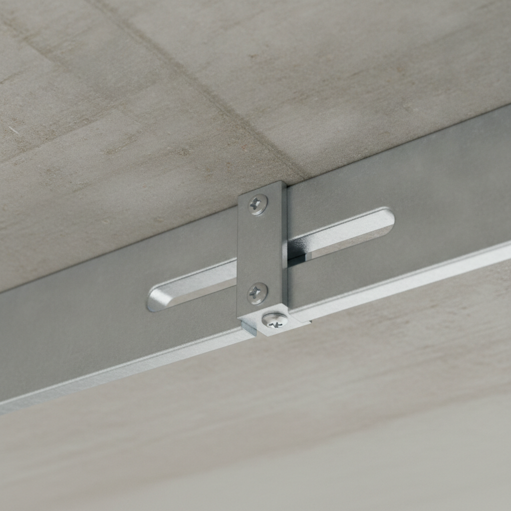
- Slotted Deflection Track: Head-of-wall slip detail that allows 1–2 in. of vertical movement while restraining lateral sway.
- Bridging / Carrying Channel: Continuous rows every 4–6 ft of height for light-gauge; closer for heavy-gauge or high walls.
- Resilient Channel: One side with mineral wool is the common acoustic spec; two sides for higher targets with careful screw control.
- Shaftwall / CH Stud: One-sided installation at elevators/mechanical shafts with rated board and tracks.
- U-Flex Track: Forms consistent curves without kerfing studs—useful in lobbies and corridors.
- Finishing Sections: 90°/130° Cornerbead, J Trim, L Trim, Z-Bar, L Track, Furring Channel for crisp edges and plumb planes.
If you’re matching legacy specs, cross-check dimensions with this quick primer on steel stud basics and our overview of drywall with metal studs.
Non-Load-Bearing vs Load-Bearing Wall Details: Choosing the Right Gauge
Use 25 ga at 24 in. o.c. for short interior partitions, step to 20 ga at 16 in. o.c. as you approach 12–14 ft, and move to 18–16 ga for load-bearing or very tall walls. Always verify against manufacturer load tables and the project engineer’s criteria.
Rules of thumb we use to short-circuit RFIs:
- Common interior: 2-1/2 in. or 3-5/8 in., 25 ga at 24 in. o.c. up to ~9–10 ft with standard gypsum.
- Taller partitions: 3-5/8 in., 20 ga (33 mil) at 16 in. o.c. past ~10 ft; add bridging mid-height.
- High or door-laden walls: Tighten to 16 in. o.c., consider 20 ga even below 10 ft when heavy doors or impact zones demand stiffness.
- Load-bearing: 18 ga (43 mil) or 16 ga (54 mil) with engineered connections, deep track, and sheathing/bracing per design.
For dimensional context on depths and thickness designations, see our quick reference on steel stud framing sizes. Then align selections with the guidance in our metal stud framing guide.
Critical Connection Details Step by Step (Track, Stud, Deflection, Bridging)
Set track straight, place studs plumb, create a 1–2 in. head-of-wall slip with slotted deflection track, then lock the line with continuous bridging. Control screw type and pattern so movement joints stay free to move and acoustic breaks stay decoupled.
Field-Proven Sequence
- Layout & track: Snap lines; fasten Standard or Deep Track to substrate per anchor schedule. Check for straightness before studs go in.
- Studs: Seat studs in base track, crown direction consistent. Hold design spacing (24 or 16 in. o.c.).
- Head-of-wall slip: Install Slotted Deflection Track with slots vertical. Use side screws into the slotted legs (not through the stud web) at the prescribed pattern so the stud can travel 1–2 in. vertically. Leave a gypsum gap at the head; finish with sealant or firestop per the rated design.
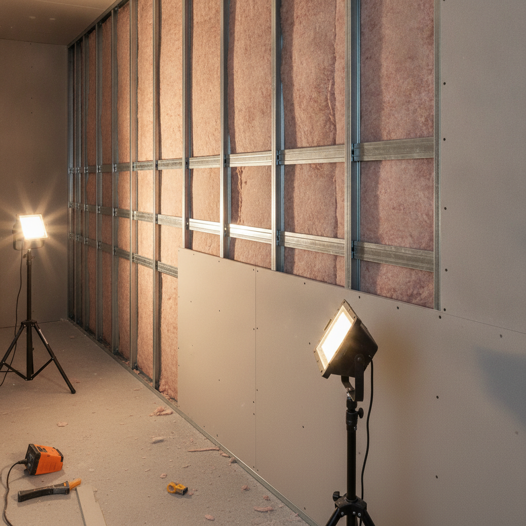
- Bridging: Install Bridging / Carrying Channel continuously using approved clips; typical light-gauge rows every 4–6 ft of height. Stagger clip locations to minimize cumulative tolerance error.
- Acoustic decoupling: If specified, mount Resilient Channel perpendicular to studs. Fasten gypsum to the channel only—do not let screws bite the studs.
Process Reference Table
| Step | Primary detail | Dass component |
|---|---|---|
| Layout & track | Base/head alignment | Standard Track / Deep Track |
| Stud install | Spacing & plumb | Light or Heavy Gauge Studs |
| Deflection | Vertical slip at head | Slotted Deflection Track |
| Stabilize | Flange restraint | Bridging / Carrying Channel |
| Acoustics | Gypsum isolation | Resilient Channel |
Need a detail check on a long run with multiple doors? Share height, stud depth, gauge, and head detail. Our team will mark up a submittal against our load data; start with these stud wall framing tips.
Acoustic and Specialty Wall Details (Resilient Channel, Shaftwall, U-Flex)
Raise STC with resilient channel on one side plus mineral wool; specify shaftwall studs for one-sided rated enclosures; and use U-Flex track to frame smooth curves. Control screw length and patterns so you don’t short-circuit decoupling or limit head movement.
Two quick scenarios:
Open office to conference room: 3-5/8 in. studs, resilient channel one side, mineral wool, and careful door jamb reinforcement. Most teams meet their target STC without adding mass if the channel is installed correctly.
Corridor with radius feature: U-Flex track keeps the radius consistent and saves finishing time over segmented cuts, especially across repeated bays.
For one-sided enclosures like elevators, see our shaftwall summary in the framing guide and coordinate rated joint treatment with firestopping. For a homeowner-focused overview of basic framing concepts, this third-party basement framing guide offers simple visuals you can share with non-technical stakeholders.
Common Detailing Mistakes and How the Right Product Prevents Them
The big four: rigid head connections, light gauges on tall spans, missing bridging, and screws that pierce studs through resilient channels. Fix them with slotted head track, heavier or closer studs, continuous bridging, and strict screw control onto channels only.
What we see in the field
- Rigid head joints: Standard track tight to slab. Result: cracks telegraph at door heads and ceiling lines after occupancy.
- Under-gauged studs: 25 ga stretched to tall heights, leading to bow and oil-canning once gypsum loads up.
- Insufficient bridging: No mid-height carrying channel; flanges twist and walls wave.
- Acoustic short-circuits: Gypsum screws bypass resilient channel into studs; STC targets missed by wide margins.
How Dass Metal Products addresses them
- Head-of-wall kits: Slotted Deflection Track allows 1–2 in. of vertical travel and keeps lateral restraint. Maintain a finish gap at the head per the rated design.
- Right gauge, right spacing: We’ll help pivot to 20 ga at 16 in. o.c. or 18 ga at 12 in. o.c. for tall runs, based on height and openings.
- Bridging guidance: We specify Bridging / Carrying Channel rows per height with compatible clips and clear spacing notes.
- Edge protection: Cornerbeads, J/L Trim, Z-Bar protect vulnerable edges and speed finishing.
Coordinating with concrete or masonry? Our affiliated resources on reinforced walls pair neatly with cold-formed framing—see foundation wall rebar details for context and terminology you’ll encounter in submittal coordination.
Frequently Asked Questions
Do all partitions need a slotted deflection track at the head?
Use slotted deflection track anywhere the partition meets a structural element that can move relative to the wall—like a floor slab. The slots and side-screw pattern let the stud travel vertically while the track holds the line laterally, protecting gypsum from cracking.
How many rows of bridging should I plan for a 12–14 ft wall?
Plan at least one continuous row at mid-height for light-gauge studs, often two rows as you approach 14 ft depending on gauge and sheathing. Continuous carrying channel with compatible clips prevents flange roll and produces flatter finishes.
Where should resilient channel be installed in an acoustic wall?
Typically on one side, perpendicular to studs, with mineral wool in the cavity. Fasten gypsum to the channel only. Doubling channels on both sides can boost performance but increases install time and requires careful screw-length control.
When do I choose deep track over standard track?
Use deep track on tall or load-bearing runs where extra leg depth improves alignment, anchorage, and tolerance. It’s also helpful on uneven substrates or where anchor edge distances demand more steel.
Key takeaways
- Design the head-of-wall as a movement joint with slotted deflection track.
- Match gauge and spacing to height and openings; tighten as spans grow.
- Use continuous bridging rows to prevent flange roll and wavy finishes.
- Decouple gypsum with resilient channel and control screw paths.
- Leverage U-Flex track and trims to speed curves and protect edges.