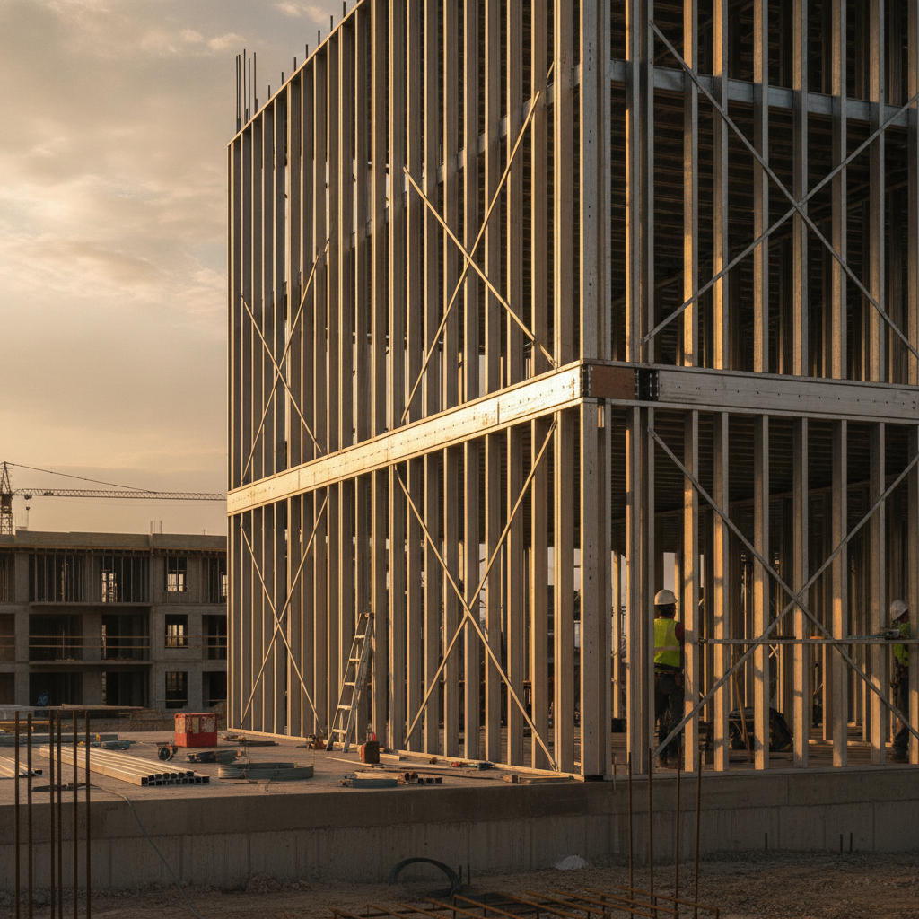
A load bearing stud wall is a structural wall framed with studs that carry axial and lateral loads from floors, roofs, or wind to the foundation. In cold-formed steel, these walls use heavy-gauge studs, structural tracks, and bracing to meet code. Getting the design and installation right protects schedules, budgets, and safety across the United States and Canada.
By Navjot Dass • Last updated: 2026-06-24
Overview
A load-bearing steel stud wall transfers gravity and lateral forces through heavy-gauge cold-formed steel studs into structural tracks and the building structure. Success depends on the right stud gauge, track type, bracing, connectors, and compliant installation—verified against project drawings, load tables, and applicable codes.
Builders, drywall and framing contractors, and design teams rely on steel for predictable strength and straightness. This complete guide explains what a load-bearing stud wall is, why it matters, how it works, and how to specify and install it correctly with real-world tips from Dass Metal Products.
- Definitions and key components
- Design logic: axial, bending, shear, and deflection
- When to use standard, deep, or slotted deflection track
- Bridging, clips, wind bracing, and acoustics
- Step-by-step field checklist and QA/QC
- Tools, resources, and examples from projects across the United States and Canada
What Is a Load-Bearing Stud Wall?
A load-bearing stud wall is a framed structural wall that supports vertical (axial) loads from floors or roofs and resists lateral loads from wind or seismic forces. In cold-formed steel, this is achieved with heavy-gauge studs, structural tracks, bridging, and connectors installed to engineered drawings.
In practice, a load bearing stud wall differs from a partition because it is part of the building’s primary structure. Heavy-gauge studs (often 16–18 ga) carry axial load; tracks collect and transfer forces; bridging limits buckling; and head-of-wall conditions accommodate movement.
- Studs: Cold-formed C-shaped members sized by width (e.g., 3-5/8 in., 6 in., 8 in.) and gauge (commonly 16–20 ga depending on load).
- Tracks: Standard, deep, or slotted deflection track depending on bearing or movement needs.
- Bracing: Bridging/carrying channel, bridging clips, and windbrace restrain stud flanges and improve stability.
- Connectors: Screws, anchors, and specialty clips (e.g., deflection side clip, webslide clip) transfer forces reliably.
For a deeper primer on cold-formed framing terminology, see our plain-language metal studs guide and the step-by-step steel stud framing guide.
Why Load-Bearing Stud Walls Matter
Load-bearing stud walls matter because they hold up floors and roofs, control lateral drift, and protect life safety. Correct gauges, tracks, and bracing reduce movement, prevent cracks, and maintain fire and acoustic performance—keeping projects on schedule and within tolerance.
Structural walls govern how a building stands and moves. Choosing the right steel stud width and gauge can tighten deflection limits, reduce shimming, and keep finishes flat. Consistent, straight studs mean faster drywall and fewer call-backs. Movement-capable head-of-wall details protect against seasonal or live-load deflection.
- Schedule impact: Walls that stay plumb and true speed boarding and taping.
- Finish quality: Lower wall wave and fewer popped fasteners improve punch results.
- Compliance: Meeting specified deflection (e.g., L/360) protects glazing, façade, and interior systems.
- Risk control: Proper anchorage and bracing reduce repair work after wind events.
If you’re moving from wood to steel in bearing walls, our steel stud wall framing overview explains key differences and why steel maintains dimensional stability through humidity swings common across North America.
How Load-Bearing Steel Stud Walls Work
Load-bearing steel stud walls work by transferring axial loads through stud webs into tracks and supports while bracing restrains buckling. Head-of-wall details manage vertical building movement, and lateral systems (sheathing, straps, or windbrace) address wind or seismic forces.
Think of each stud as a slender column. Axial load capacity depends on the stud’s effective length, braced spacing, thickness (gauge), and section properties. Bridging installed at regular intervals shortens the unbraced length and raises capacity. Tracks act as collectors; anchors connect the system to concrete or structural steel.
- Axial design: Select stud size/gauge for dead + live load, including eccentricities at top/bottom connections.
- Lateral stability: Use bridging channel with clips at set spacing (e.g., 4 ft. o.c. typical engineering guidance) to restrain flanges.
- Head-of-wall: For movement, use a slotted deflection track; for fixed bearing, use standard or deep track.
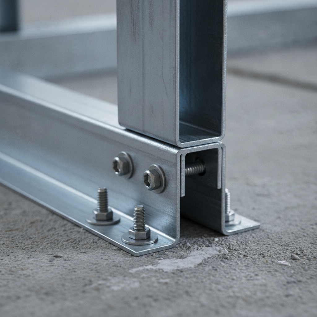
- Anchorage: Provide adequate screw patterns and anchor embedment to develop required loads.
- Finish systems: Where acoustics matter, resilient channel and proper insulation reduce flanking paths.
We detail these mechanics in our steel building studs overview and interior stud wall framing guide, which many field teams use as quick refreshers before layout.
Types, Methods, and Approaches
Choose the wall approach by movement and load: fixed-bearing with standard or deep track for full load transfer, or head-of-wall deflection with slotted track where vertical movement is expected. Add bridging, clips, and wind bracing to reach the engineered capacities.
Different assemblies serve different constraints. Fixed-bearing walls provide direct load paths; deflection heads protect brittle finishes below moving structures. Deep track improves stud end restraint and simplifies layout; slotted deflection track introduces slip capacity without compromising alignment.
- Fixed-bearing walls: Use standard or deep track where movement is negligible; ensure solid bearing and full screw patterns.
- Deflection head-of-wall: Use slotted deflection track to accommodate vertical movement from live load or creep.
- Bracing strategies: Bridging channel + clips, windbrace straps, and sheathing act together to limit sway and buckle.
- Acoustic layers: Resilient channel and mineral wool reduce transmission while preserving structural paths.
| Condition | Recommended Track | Primary Benefit | Notes |
|---|---|---|---|
| Fixed bearing | Standard track | Direct load transfer | Verify anchor spacing and screw pattern. |
| Heavier loads/alignment | Deep track | Improved end restraint, easier layout | Useful for thicker sheathing and tolerances. |
| Movement needed | Slotted deflection track | Vertical slip capacity | Prevents finish cracking under live-load deflection. |
For a broad view of profiles and sizes used in the field, this explainer on steel stud framing sizes is a helpful reference during early coordination.
Best Practices for Design and Installation
Confirm loads, choose the right stud width and gauge, restrain flanges with bridging, select an appropriate track, and verify anchors and screw patterns. Document inspections at layout, mid-height bracing, and close-in to keep quality, safety, and compliance on track.
We’ve seen the same field truths repeat: clear shop drawings, consistent layout, and timely inspections eliminate most rework. Below is a pragmatic checklist you can hand to crews and use during pre-pour or pre-board walk-throughs.
- Preconstruction
- Confirm axial + lateral loads and drift limits with the engineer of record.
- Select stud width (e.g., 6 in. or 8 in.) and gauge to meet strength and serviceability.
- Decide on standard, deep, or slotted deflection track for head-of-wall conditions.
- Plan bridging locations (e.g., 4 ft. o.c. rows) and clip types.
- Layout
- Snap lines for track centerline; verify openings and penetrations.
- Ensure base track anchors meet structural notes and embedment guidance.
- Use story poles/templates to maintain stud spacing (often 16 in. o.c. in bearing walls).
- Framing
- Seat each stud fully in track; check plumb with laser/level.
- Install bridging channel and clips at the specified elevations.
- At deflection heads, keep screws in slots per drawings to preserve slip.
- Close-in
- Confirm screw patterns at sheathing and gypsum per schedule.
- Inspect firestopping and sealants at head-of-wall joints.
- Record as-builts and photo logs before concealing work.
Need a refresher on bearings versus partitions? Our practical steel wall studs guide covers selection logic crews can apply on day one.
Tools and Resources
Use shop drawings, load tables, product brochures, and field checklists to streamline decisions. Pair these with manufacturer guidance on track, bridging, clips, and head-of-wall details so crews can execute consistently and pass inspections the first time.
Teams that standardize documentation tend to deliver repeatable quality. Keep a digital binder with submittals, typical details, and checklists. It shortens RFI cycles and speeds onboarding for new team members.
- Design aides: Stud and track load tables, typical details, and shop drawings for review and stamping.
- Field references: Install sequences, inspection checklists, and approved screw/anchor schedules.
- Coordination notes: Movement joints, firestopping at head-of-wall, and acoustic layers where required.
- Further reading: Explore our tag hub on load-bearing studs for focused how-to articles.
For a broader understanding of related reinforcement, this rebar stirrups guide explains shear reinforcement logic that complements cold-formed framing around cores and slabs.
Case Studies and Examples
Real-world bearing walls succeed when gauges, tracks, and bracing match the loads and details. The best outcomes come from coordinated shop drawings, consistent bridging, and movement-tolerant heads—and crews who inspect before close-in.
Multistory corridor wall, heavy-gauge studs: A contractor standardized 6 in., 16 ga studs with deep track and bridging at 4 ft. o.c. Using a slotted head at the top of wall protected tile and glazing from live-load deflection. The result: faster board, fewer finish repairs.
Mechanical shaft, CH stud system: In a mixed-use tower, a shaftwall assembly with CH studs provided one-sided installation and fire-resistance continuity. Coordinating openings with MEP reduced field modifications and improved inspection outcomes.
- Define the governing limit state (strength versus serviceability) early.
- Pick stud width/gauge from approved load tables and confirm bridging rows.
- Use deflection heads under flexible structures to prevent finish damage.
- Log inspections at layout, mid-height bracing, and final close-in.
If you’re building a training library for new superintendents, bookmark our steel stud wall framing walkthrough; it pairs well with the broader steel building studs overview for context.
Frequently Asked Questions
These concise answers address the most common questions teams ask about load-bearing steel stud walls—focused on movement, sizing, bracing, and inspection so you can make quick, informed decisions in the field.
What gauge should I use for a load bearing stud wall?
Select gauge based on axial and lateral loads plus bracing and unbraced length. Heavy-gauge (often 16–18 ga) is typical for bearing walls, but always verify with engineered load tables and the project drawings before ordering.
When do I need a slotted deflection track at the head of wall?
Use a slotted deflection track when the structure above can move under live load, creep, or temperature. The slots allow vertical slip so finishes don’t crack. Where movement is negligible, a fixed-bearing standard or deep track is appropriate.
How far apart should bridging rows be?
Follow the engineered drawings. Many designs use bridging/carrying channel rows at roughly 4 ft. on center to restrain stud flanges and increase axial capacity, but spacing depends on stud height, gauge, and the required capacity.
Does resilient channel help on load-bearing walls?
Yes—where acoustic control is required, resilient channel can decouple gypsum from studs to reduce transmission. It doesn’t replace structural components; use it alongside proper gauges, bracing, and head-of-wall details.
Conclusion
Successful load-bearing steel stud walls start with verified loads, the right gauge and track, disciplined bridging, and movement-aware heads. Standardize your checklists, document inspections, and partner with an experienced manufacturer to keep quality predictable.
In our experience supporting builders across the United States and Canada, the most reliable projects follow a repeatable playbook: confirm loads and drift, choose profiles and tracks from approved submittals, install bridging on time, and inspect before you close in. That rhythm protects schedules and elevates finish quality.
Key Takeaways
- Define loads and drift before sizing studs and tracks.
- Use deep track for alignment and slotted track for movement.
- Install bridging rows on schedule to restrain flanges.
- Document inspections at layout, mid-height, and close-in.
- Leverage manufacturer resources to speed decisions.
Ready to move from questions to action? Share your drawings with our team. We’ll help you select profiles and details for your next load bearing stud wall so crews can frame confidently and pass inspections the first time.
Related Articles
For broader context on studs and framing fundamentals, our articles on steel stud framing and metal studs expand on terminology, selection, and field tips that pair well with this guide.