A steel framing system is a coordinated set of cold‑formed steel studs, tracks, channels, and clips that create straight, durable walls, ceilings, and enclosures. It delivers predictable strength, fire and acoustic performance, and fast installation. Based in 370 New Enterprise Way (Vaughan, ON), Dass Metal Products engineers systems that keep Ontario, Canada, and U.S. jobsites on schedule.
By Navjot Dass — Dass Metal Products
Last updated: 2026-05-25
Quick Summary and Table of Contents
Steel framing systems combine steel studs, tracks, and connectors into code-compliant walls and ceilings. Choose gauge by load and height, manage movement with deflection detailing, and use resilient channels for acoustics. This guide explains what it is, why it matters in 2026, how it works, best practices, and actionable checklists.
Here’s what you’ll learn and how to navigate this complete guide tailored to builders, drywall contractors, and specifiers working with Dass Metal Products.
- What it is: Definitions, components, and how cold‑formed members interact.
- Why it matters in 2026: Schedule certainty, labor efficiency, and performance under evolving codes.
- How it works: Framing sequence, spacing (16 or 24 inches o.c.), and connection details.
- Types and components: Light and heavy gauge studs, standard, deep, and slotted deflection tracks, resilient and bridging channels, shaftwall CH studs, and trims.
- Best practices: Member selection by height and load, drift allowances (commonly up to 1 inch), fastener choices (#8/#10), and QA/inspection habits.
- Tools and resources: Load tables, product brochures, standards, and submittal templates tied to Dass Metal’s catalog.
- Case examples: Real scenarios from Ontario commercial interiors and cross‑border deliveries.
Use the mini-TOC to jump to what you need now:
- What Is a Steel Framing System?
- Why It Matters in 2026
- How It Works
- Types and Components
- Best Practices
- Installation & QA
- Performance
- Tools & Resources
- Pricing Considerations
- Case Studies
- FAQ
- Conclusion & Next Steps
What Is a Steel Framing System?
A steel framing system is a coordinated assembly of cold‑formed steel studs, tracks, channels, and clips that transfers loads, controls movement, and supports finishes. Members are roll‑formed in specific gauges and dimensions, installed at set spacing (often 16 or 24 inches o.c.), and detailed to meet fire, acoustic, and drift requirements.
At its core, a system organizes light and heavy gauge components so drywall, sheathing, and façade elements have stable backing. Studs provide vertical support; tracks guide alignment; channels control bracing and acoustics; and clips resolve movement. When you view framing as a system, choices about gauge, spacing, and connections become easier—and documentation stays consistent.
Dass Metal manufactures both non‑load‑bearing and load‑bearing members, plus purpose‑built accessories. For a primer on wall layout and typical spacing patterns, see our internal overview of metal framing systems. For wall framing specifics, our steel stud wall framing deep‑dive explains common heights, door rough openings, and screw sequences used across Ontario interiors.
System thinking reduces rework. For example, pairing a slotted deflection track with a deflection side clip keeps the stud free to slip under vertical live load or wind‑induced drift from the structure above. A 1/2 to 1 inch slip allowance is typical for mid‑rise interiors, while exterior infill can require larger values based on drift analysis.
Documentation matters too. Submittals that include member labels, gauges, spacing, and head/ jamb/ base details help inspectors and GCs audit quickly. Clearly defined assemblies—like “3‑5/8″ 20 ga studs at 16″ o.c. with slotted head track”—cut RFI volume and speed approvals.
Why Steel Framing Matters in 2026
Steel framing matters because it speeds schedules, stabilizes quality, and meets modern fire, acoustic, and movement requirements. In 2026, supply reliability and engineered documentation reduce site risk. Dass Metal’s CSSBI‑certified products and cross‑border delivery keep multi‑site programs on time.
Construction schedules are tighter, documentation is stricter, and building owners expect durable, low‑maintenance finishes. Cold‑formed steel delivers dimensional stability—studs don’t warp, shrink, or split—so drywall stays flat. That reduces call‑backs and finish repairs. Standardized gauges and punch patterns also improve MEP coordination, which cuts rough‑in conflicts.
Labor efficiency is real. Pre‑punched knockouts speed cable and conduit runs, and consistent flange widths improve screw “bite.” In interiors, 16 or 24 inches on center remains the dominant pattern; ceilings and soffits often adopt 12 inches where high point loads or long spans occur. Organized material drops and consistent screw counts per joint translate to predictable daily output per crew.
Risk control matters. Movement detailing at the head (slotted track), base (weep or isolation), and penetrations (sealant break) prevents cracking as structures deflect under live load or wind. Acoustic targets (STC ratings) push resilient channel and double‑layer drywall; shaftwalls combine CH studs and gypsum liner panels to protect vertical services. These assemblies standardize compliance paths for plan checkers and insurers.
Dass Metal adds a supply‑chain edge: Canadian manufacturing near 370 New Enterprise Way supports regional jobs and dependable lead times. Engineering support (40+ years) helps specifiers convert design intent into buildable details. For a forward look at safety and schedule drivers, see our perspective on why steel framing matters.
How a Steel Framing System Works
Steel framing works by transferring vertical and lateral loads through studs into tracks, then into the structure. Bracing and channels control buckling and vibration. Head‑of‑wall slip details accommodate deflection, and proper screw patterns ensure composite action with finishes.
Most wall assemblies follow a clear sequence:
- Layout: Snap lines, verify finished floor elevations, and confirm stud heights (add head slip as needed).
- Track set: Install base and head tracks; use slotted deflection track where drift or live load is expected.
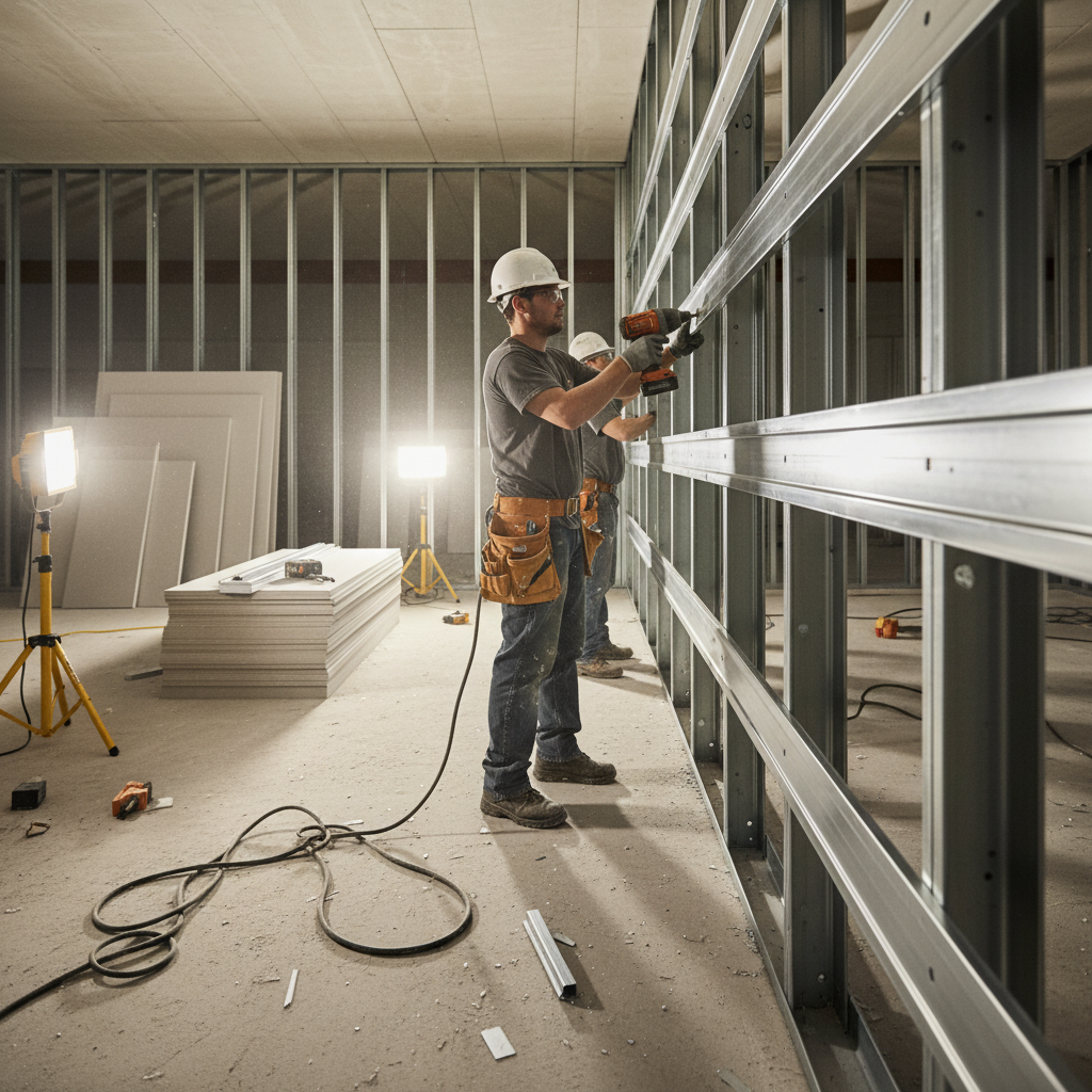
- Stud install: Plumb studs at 16 or 24 inches o.c.; seat snugly without pinning top flanges when using slots.
- Bracing: Add bridging/carrying channel or flat straps to control rotation on taller walls.
- Openings: Frame jambs and headers; use heavier gauges around doors and glazing.
- MEP: Route through pre‑punched knockouts; add grommets where required by spec.
- Boarding: Fasten gypsum per pattern (e.g., 8 inches o.c. at edges, 12 inches in field is common).
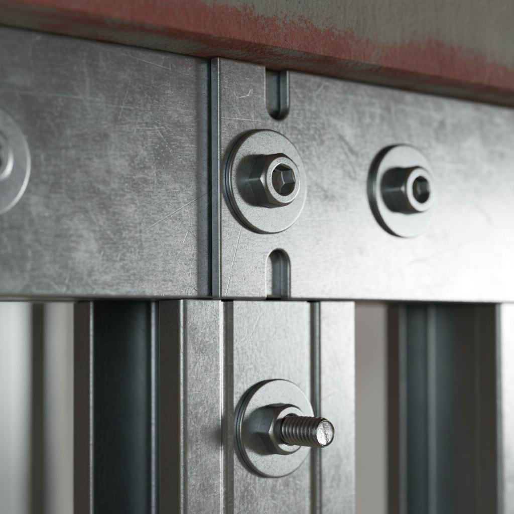
Connections make the system. #8 pan‑head screws handle most interior studs; exterior or thick members may call for #10 or self‑drilling types. Where floors are uneven, deep track at the base helps absorb tolerances. In stair cores and shafts, CH studs interlock with liner panels for fire and smoke separation without back‑framing.
Movement is non‑negotiable. Head details must permit the structure to deflect without transferring loads into non‑load‑bearing walls. A typical slip of 1/2 to 1 inch through slotted track and clips is common, but always confirm with the structural engineer. For exterior infill, drift limits drive larger slots or proprietary connectors.
For wall and ceiling fundamentals—plus time‑saving field tips—see our practical steel studs guide.
Types of Steel Framing Systems and Components
Steel framing systems include non‑load‑bearing and load‑bearing walls, ceilings, soffits, and shafts. Core components are studs, tracks (standard, deep, slotted), channels (resilient, bridging), clips, and trims. Selecting gauge, spacing, and detailing depends on height, loads, acoustics, and movement.
Dass Metal’s catalog is engineered for complete systems—interior framing, exterior infill, acoustic control, and finishing. Below is a practical map you can use on submittals and takeoffs.
Studs and Track (The Backbone)
- Non‑Load‑Bearing Steel Studs (Light Gauge): Common depths include 1‑5/8″, 2‑1/2″, 3‑5/8″, 4″, and 6″. Typical spacing is 16 or 24 inches o.c. Use light gauges in interiors where studs support only gypsum and MEP.
- Load Bearing Stud Framing (Heavy Gauge): Heavier members carry axial loads; headers and jambs around openings often step up in gauge. Explore member options on the load‑bearing stud framing system page.
- Standard Track: Guides stud alignment at base and head; choose leg height to match stud flanges. Deep track can absorb floor variation.
- Slotted Deflection Track: Allows vertical slip at the head. For detailing guidance and field do’s/don’ts, see our internal slotted deflection track guide.
- Deep Track: Extra leg depth helps manage uneven slabs or large tolerances at the base.
Channels and Bracing (Control and Performance)
- Bridging / Carrying Channel: Limits rotation and buckling on taller walls; combine with bridging clips or flat straps.
- Resilient Channel: Decouples gypsum from framing to raise STC ratings; install perpendicular to studs with screws only into the channel flange.
- Furring Channel: Levels surfaces, supports cladding, or creates cavities for acoustic insulation.
Clips and Connectors (Make or Break)
- Deflection Side Clip: Creates slip at jambs and partitions intersecting structural elements.
- Webslide or Bridging Clips: Speed bridging install and standardize spacing.
- Windbrace: Adds lateral resistance on select assemblies; confirm with engineering calcs.
Drywall Finishing Sections (Quality at the Finish)
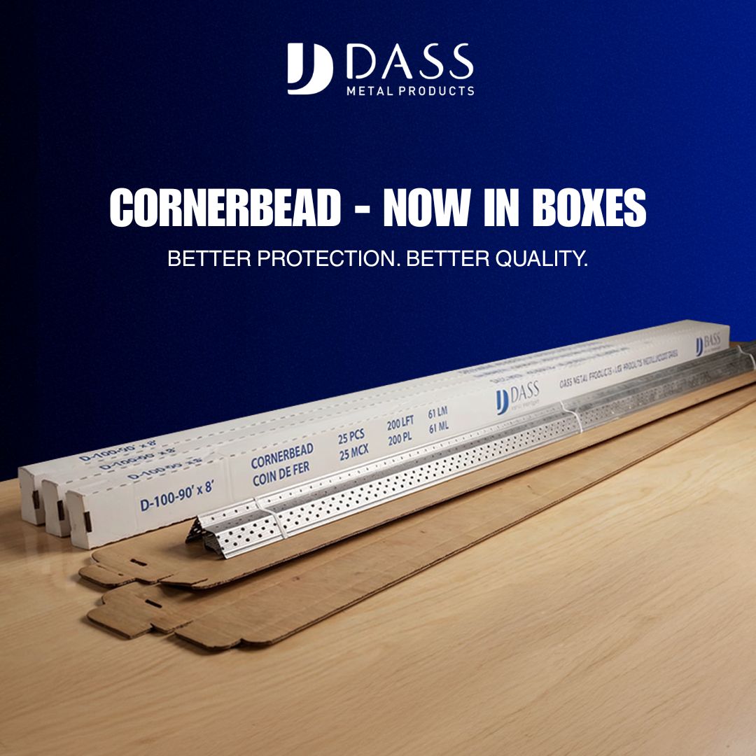
- 90°/130° Cornerbead: Protects exposed edges; 130° helps on off‑angle conditions.
- L Trim, J Trim, J Track: Clean terminations at ceilings, windows, and material transitions.
- U‑Flex Track: Curvable track for radius walls; verify radii limits before layout.
For dimensional references and common sizes used in Canada, see the practical overview of steel stud framing sizes. For light‑gauge application notes, the primer on light gauge steel framing covers spacing, backing, and boarding patterns typical to commercial interiors.
Best Practices for Design and Specification
Select members by wall height, load path, and performance targets. Document spacing (16 or 24 inches o.c.), gauge, and head/base details. Use slotted track where drift or live load is present, resilient channel for STC, and bridging at intervals to control stud rotation on tall walls.
In our experience, the most reliable submittals follow a consistent pattern: call out stud depth and gauge, track type, spacing, and head/base details in a single line. Example: “3‑5/8″ 20 ga studs @ 16″ o.c.; slotted head track with 3/4″ slip; deep base track; RC‑1 resilient channel @ 24″ o.c.” That single sentence clarifies multiple inspection points.
- Member selection: Taller or loaded walls push gauges up. Non‑load‑bearing partitions commonly use light gauge; door jambs often step heavier to manage hardware loads.
- Head‑of‑wall detailing: If structural deflection is expected, slotted track plus clips avoids screw binding. Avoid pinning studs to the slotted head.
- Bridging intervals: Add carrying channel or straps per engineered spacing on tall walls to limit twist.
- Acoustics: Use resilient channel and insulation to meet STC targets; fasten gypsum only to the channel flange to maintain decoupling.
- Exterior infill: Coordinate drift limits early; connectors and slot lengths must match the lateral design.
- Documentation: Keep load tables and product data in one PDF bundle. Inspectors move faster when every component is labeled and cross‑referenced.
For a spec framework that aligns with real‑world field constraints, review our internal framing systems specification guide.
Installation Workflow and QA Checklist
Organize materials, set tracks, plumb studs at 16/24 inches o.c., brace tall walls, and protect movement joints. Verify screw types, slot clearance, and gypsum patterns. A short daily QA checklist prevents cracks, out‑of‑plumb walls, and failed acoustic targets.
Step‑by‑Step Field Workflow
- Staging: Drop studs by zone; confirm lengths (add 1/2–1 inch for slip at head if required).
- Head and base tracks: Laser align; anchor per substrate. Use deep track on uneven floors.
- Stud install: Insert studs square; keep a hairline gap below the head slots.
- Openings: Heavier jambs and headers around doors; confirm clearance for frames and hardware.
- Bridging: Install carrying channel or straps at engineered intervals.
- MEP rough‑in: Route through factory knockouts; protect with grommets where specified.
- Boarding and RC: Fasten gypsum per pattern; when using resilient channel, avoid short‑circuiting with errant screws.
Five‑Minute Daily QA
- Randomly check stud spacing at several bays (target 16 or 24 inches o.c.).
- Verify slip clearance at each head detail (commonly 1/2–1 inch unobstructed).
- Spot‑check screw types (#8 interior; #10 for thicker members or exterior).
- Confirm bridging placement and tightness.
- Inspect resilient channel lines for level and proper fastener placement.
For hands‑on tactics that crews adopt quickly, our practical notes in the steel stud wall framing overview pair well with superintendent checklists.
Performance: Acoustics, Fire, and Movement
Performance hinges on three things: decoupling for acoustics, fire‑rated assemblies for life safety, and movement joints for deflection. Resilient channels raise STC, shaftwall CH studs form protected chases, and slotted head details prevent cracking as structures move.
Acoustics (STC): Resilient channel adds a flexible layer between studs and gypsum. Typical patterns are 24 inches o.c. horizontally, but always follow assembly listings. Insulation in stud cavities improves mid‑frequency attenuation; double‑layer gypsum increases mass for low‑frequency control. Remember: one misplaced screw into a stud can “short” the resilient path and drop STC.
Fire: Rated assemblies use specific layer counts, fastener spacing, and joint treatments. Shaftwalls—combining CH studs with liner panels—protect vertical utilities and elevator cores while allowing one‑sided installation from the corridor. Keep screw type, spacing, and board orientation identical to the listing to maintain the rating.
Movement: Buildings deflect under live loads and wind. Head‑of‑wall slots and deflection side clips maintain a continuous fire and smoke barrier while letting the wall slip. Base details can include sealant breaks or slip membranes to isolate finishes from slab curling or moisture.
Tools, Resources, and Standards
Use manufacturer load tables, product data sheets, and assembly listings to align design intent with field reality. Centralize submittals, detail sheets, and QA checklists. Dass Metal provides brochures, standards, and engineering support for light and heavy gauge systems.
- Load and span tables: Keep current tables for typical stud depths and gauges at common spacings (16/24 inches o.c.).
- Product data sheets: Maintain a single folder for tracks (standard, deep, slotted), channels (resilient, bridging), and clips (deflection, webslide, bridging).
- Assembly listings: Fire and acoustic assemblies are only valid when fasteners, spacing, and board types match the listing.
- Field templates: Head‑of‑wall details; RC installation diagrams; door jamb reinforcement notes.
You can browse a system overview at our internal metal framing systems guide and review light‑gauge application notes in the light‑gauge studs article. For a high‑level look at sizes used across projects in Canada, the steel stud sizes reference is a helpful orientation.
Local considerations for 370 New Enterprise Way
- Plan winter deliveries with indoor staging in the Vaughan area to prevent condensation on galvanized members before boarding.
- Coordinate holiday and construction rush periods; drywall crews often book out early in Q4, so confirm framing drops and inspections in advance.
- For Ontario projects with cross‑border components, align submittals to both Canadian and U.S. expectations so approvals don’t bottleneck logistics.
Pricing Considerations (Without Numbers)
Price outcomes depend on gauge selection, spacing, detailing, and logistics. Optimize total installed value by matching member sizes to height and load, minimizing rework through clear details, and staging deliveries so labor hours convert efficiently to linear feet framed.
Here’s how teams protect budgets without chasing unit prices alone:
- Right‑size members: Oversizing studs and headers adds weight and screws; undersizing invites deflection and repairs.
- Detail clarity: Slotted head details and RC patterns prevent cracking and acoustic failures that trigger rework.
- Logistics: Sequenced drops reduce material handling. Cross‑border delivery keeps multi‑state and Canadian schedules aligned.
- QA habits: Five‑minute checks on spacing, slip clearance, and screw types avert days of reboard.
For heavy‑gauge options used where loads or spans drive decisions, see the load‑bearing framing system overview. For interiors, light‑gauge standards in the light gauge framing primer explain why 16/24 inches o.c. patterns dominate labor planning.
Case Studies and Examples
Real projects show how gauge, spacing, and detailing drive results. In Ontario interiors, light‑gauge studs at 16 inches o.c. with slotted head details reduced cracking and punch‑list time. Cross‑border deliveries kept multi‑site retail rollouts aligned without schedule slips.
Ontario commercial interiors (non‑load‑bearing)
- Challenge: Fast‑track build‑out with tall corridor walls.
- Solution: 3‑5/8″ studs @ 16 inches o.c., slotted head track with 3/4″ slip, carrying channel at engineered intervals.
- Result: Straight walls, clean reveals, and no head cracking after ceiling loads were added.
Retail program with U.S. sites (logistics)
- Challenge: Keep framing consistent across provinces and states.
- Solution: Standardized submittal templates and coordinated deliveries from Dass Metal’s Canadian plant to U.S. jobsites.
- Result: Predictable installation rates, reduced RFIs, and synchronized openings.
Shaftwall and core areas
- Challenge: Protect vertical utilities and meet ratings without back‑framing.
- Solution: CH studs with liner panels, detailed head movement, and strict screw patterns.
- Result: Inspections passed on first visit; elevator openings framed to exact hardware tolerances.
At‑a‑Glance Comparison of Common System Choices
| Application | Typical Member | Gauge Range | Spacing | Notes |
|---|---|---|---|---|
| Interior partition | 3‑5/8″ stud + standard track | Light gauge | 16″ or 24″ o.c. | Use slotted head where deflection expected |
| Tall corridor wall | 4″–6″ stud + carrying channel | Light to heavier | 16″ o.c. typical | Engineer bridging intervals to limit twist |
| Door opening | Heavier jamb/header | Heavier | Match wall | Reinforce for hardware loads |
| Acoustic partition | Stud + resilient channel | Light to medium | RC at 24″ o.c. | Don’t short RC with screws |
| Shaftwall | CH stud + liner | System specific | System specific | One‑sided install from corridor |
Need a second set of eyes on your submittal? Share your wall heights, spacing, and performance targets. Our engineering team (40+ years) will help right‑size members and head details so your crews move faster.
Frequently Asked Questions
These quick answers cover selection, spacing, movement, and acoustics for steel framing systems. They’re practical pointers you can hand to crews and estimators today.
What’s the difference between light and heavy gauge studs?
Light gauge studs frame non‑load‑bearing walls and ceilings; heavy gauge studs carry structural or concentrated loads like headers and jambs. Use light gauge for most interiors and step up at openings or tall spans per engineering tables.
Should I choose 16 inches or 24 inches on center?
For interiors, 16 inches on center is common where finishes or height demand stiffness. Many partitions use 24 inches for speed and material savings when assemblies permit it. Follow assembly listings and the engineer’s span limits for your stud depth and gauge.
When do I need slotted deflection track?
Use slotted head details when the structure above is expected to deflect under live loads or wind. The slots and clips let non‑load‑bearing walls move without cracking. Coordinate slip allowance—often 1/2 to 1 inch—with the structural engineer.
How does resilient channel improve acoustics?
Resilient channel decouples gypsum from the stud, reducing vibration transfer and raising STC. Install channels perpendicular to studs, typically at 24 inches o.c., and fasten board only to the channel flange. Avoid accidental screws into studs, which short the system.
Conclusion and Next Steps
Build faster, straighter, and safer by treating steel framing as a system. Right‑size members, detail head movement, use resilient channels for acoustics, and keep documentation tight. Dass Metal’s Canadian manufacturing, CSSBI certification, and engineering support help you deliver on schedule.
- Key takeaways: System thinking prevents rework; spacing drives labor; movement details stop cracks; RC boosts STC; documentation speeds approvals.
- Action steps: Draft a one‑line spec per wall, bundle data sheets, confirm slip allowances, and stage materials by zone.
- Get help: Share heights, spacing, and performance targets. We’ll align gauges, tracks, and channels to your schedule.
Explore deeper how‑tos in our steel studs guide and the broader metal framing systems overview. When you’re ready, we can coordinate dependable deliveries across Ontario, Canada, and the U.S.