Metal framing systems are coordinated cold-formed steel studs, tracks, channels, and clips assembled into code-aligned walls, ceilings, and soffits. At 370 New Enterprise Way in Vaughan, Dass Metal Products engineers and supplies complete systems across Canada and the U.S., helping contractors install faster with predictable quality, documented performance, and dependable delivery.
By Navjot Dass • Dass Metal Products
Last updated: April 27, 2026
Above-Fold Hook + Table of Contents
This complete guide explains how metal framing systems speed installation, reduce rework, and meet code on day one. You’ll get clear definitions, component breakdowns, selection checklists, and field-proven practices—grounded in Dass Metal Products’ real manufacturing, engineering support, and cross-border delivery experience.
Speed and certainty win schedules. If you want straighter walls, cleaner MEP coordination, and reliable lead times, you’re in the right place. Here’s what we’ll cover.
- What metal framing systems are and when to use them
- Why systems matter for speed, acoustics, and compliance
- How studs, tracks, and channels work together
- Types, methods, and selection approaches
- Best practices that prevent rework
- Tools, resources, and standards for fast approvals
- Mini case studies and practical examples
- FAQ and next steps
Quick Summary
Metal framing systems combine compatible studs, tracks, channels, and clips from one engineered family. The result is faster layout, fewer RFIs, and straighter finishes. Select components for load, acoustics, and deflection; document details up front; and stage materials by zone to keep inspections smooth and board-up predictable.
In our experience, coordinated systems save hours per zone because dimensions, hole patterns, and movement details match across SKUs. Typical partition spacing is 16 or 24 inches on center, with gauges ranging from 25 to 16 and common stud depths from 1-5/8 to 6 inches. Those specifics make planning tangible—and repeatable.
What Is a Metal Framing System?
A metal framing system is a coordinated set of cold-formed steel components—studs, tracks, channels, clips, and trims—designed to frame interior and exterior walls, ceilings, soffits, and shafts. The system approach ensures compatibility, code alignment, and faster installation than mixing unrelated parts.
In practice, the “system” idea means parts are designed to work together: studs seat in tracks; channels brace flanges; clips manage movement; trims protect edges. When the dimensions, hole patterns, and fastener assumptions align, layout stays crisp and crews move without second-guessing details.
- Core elements: non-load-bearing studs, load-bearing studs, standard track, deep track, slotted deflection track, bridging/carrying channel, resilient channel, connectors and clips, and drywall finishing trims.
- Typical numbers: 16 or 24 inches on center for stud spacing; gauges from 25 (light) to 16 (heavy); head-of-wall deflection commonly designed to L/240–L/480 limits depending on assembly intent.
- Why it matters: coordinated SKUs reduce tolerance conflicts, speed inspections, and help prevent cracking at head-of-wall or waviness in tall partitions.
For context, our team supports specs with imperial and metric load tables, MSDS, and standards in a single submittal set—so field questions get answered without delay. That structure is what keeps schedules honest.
For a broader framing perspective, see our pillar resource on strategies in the steel framing guide (internal overview of best practices).
Why Metal Framing Systems Matter
Metal framing systems deliver straighter walls, predictable schedules, and documented capacities. Crews rely on consistent dimensions, pre-punched knockouts, and engineered deflection details that integrate cleanly with fire, sound, and movement requirements in modern codes.
Here’s the thing: schedules slip when materials vary. Steel studs arrive uniform, with gauge, width, and length tightly controlled. Pre-punched knockouts align with MEP routing, so fewer studs are drilled on site. That reduces damage and keeps conduit and piping where drawings expect them.
- Speed and repeatability: standard stud sizes (e.g., 3-5/8 inches), consistent crowns, and straight lines reduce layout time and rework.
- Acoustics: resilient channel decouples drywall to improve STC ratings; target STC 50+ is common in multifamily and hospitality assemblies.
- Movement: slotted head-of-wall tracks or side clips accommodate vertical deflection at the deck, protecting gypsum finishes from cracks.
- Documentation: unified data sheets and load tables simplify RFIs and approvals, cutting days from review cycles.
Our internal data from repeated Ontario and cross-border fit-outs shows fewer punch-list line items when crews standardize on one compatible system family. Inspectors respond well to consistent details backed by clear tables.
To understand where steel edges out wood for speed and stability, see when steel studs beat wood for interior work (internal comparison).
How Metal Framing Works
Studs seat into tracks fastened to floors and decks; bridging channels brace flanges; and deflection tracks or clips allow vertical movement. The result is a predictable substrate for drywall or sheathing that remains plumb, quiet, and crack-resistant over time.
Most interior partitions start with layout lines, then track fastening, and then stud placement at 16 or 24 inches on center. For taller spans, bridging/carrying channel adds stiffness and controls twist. Where the slab or roof can move, slotted deflection tracks or side clips decouple the wall to maintain finish integrity.
- Layout: snap chalk lines; verify doors, frames, and penetrations before fastening. Typical track fastener spacing runs 12–24 inches depending on substrate and assembly.
- Anchorage: select anchors by substrate (concrete, steel, wood) and by fire/sound requirements; #8 or #10 screws are common for many connections.
- Bracing: install bridging channel at prescribed intervals (often 4–8 feet vertically) to manage slenderness and maintain flat planes.
- Movement: head-of-wall deflection slots commonly allow 1 inch or more of vertical slip; confirm per design criteria.
We recommend a two-minute checklist before board-up: confirm stud spacing, track fastener pattern, bridging intervals, and head-of-wall details. Capture photos and attach the submittal page references. That small habit saves hours during inspection.
For a deeper dive into bracing logic and layout intervals, our internal primer on steel frame bracing outlines field-proven setups (internal).

Types, Components, and Approaches
Metal framing systems include light and heavy gauge studs, standard, deep, and slotted deflection tracks, bridging and resilient channels, and a range of clips and trims. Choosing among them aligns structure, acoustics, tolerance, and movement control with design intent and inspection expectations.
Studs and Tracks (Light vs. Heavy Gauge)
Match stud depth and gauge to span, load, and finish quality. Typical light-gauge studs include 1-5/8, 2-1/2, 3-5/8, and 6 inches in depths with gauges from 25 to 20. Heavy-gauge, load-bearing studs run deeper and thicker, with axial and lateral capacity for exterior or shaft walls.
- Non-load-bearing studs (light gauge): the workhorse for interior partitions; 16 or 24 inches on center; fast to cut, light to carry.
- Load-bearing studs: heavier gauges and deeper sections for axial and lateral demands; coordinate with the structural schedule.
- Standard track: baseline where the head is fixed; use where no vertical deflection is expected.
- Deep track: added leg depth for easier stud insertion, tolerance take-up, or specific substrates; helpful near uneven slabs.
- Slotted deflection track: elongated slots permit vertical slip between wall and deck; protects finishes from structural movement.
If you’re weighing heavy-gauge options for exterior or shafts, our product overview on load-bearing stud framing (internal catalog page) outlines typical profiles and selection logic.
Channels and Clips (Control, Stability, and Speed)
Channels and clips are small components with oversized impact. Correct bridging intervals keep tall walls plumb. Resilient channel boosts STC performance by decoupling drywall. Side clips maintain spacing and enable slip where slotted tracks aren’t feasible.
- Bridging/carrying channel: braces studs to limit twist and buckling; often installed at 4–8 foot vertical intervals depending on design.
- Resilient channel: decouples board from framing to improve STC—common in multifamily and hotels striving for STC 50+ between dwelling units.
- Deflection side clips: allow vertical slip where head conditions or sequencing call for clip-based movement control.
- Webslide and bridging clips: speed installation and lock spacing without over-tightening.
- Windbrace: diagonal steel strapping that adds lateral stability to partitions subject to out-of-plane loads.
Where sound control is the priority, review our internal note on non-structural framing details that interact with sealants and insulation (internal overview).
Finishing and Specialty (Trims and Radiuses)
Finishing profiles ensure clean edges and long-term durability. Specialty shapes also unlock design intent—curved walls, shafts, and service chases get simpler when trims and flexible tracks are part of the same system family.
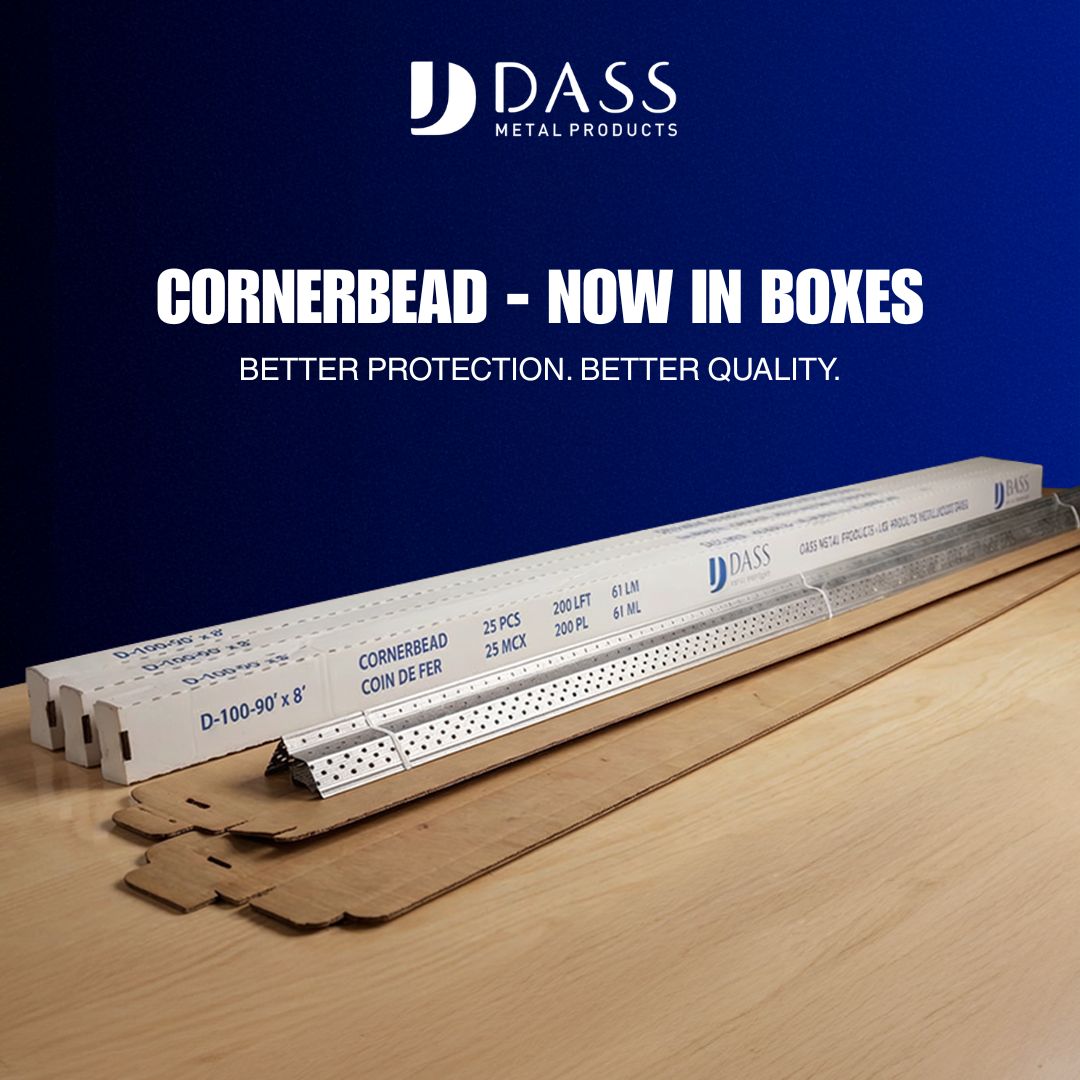
- Cornerbead (90°/130°), J/L trims, and J track to protect corners, edges, and transitions.
- Furring channel and Z-bar to level surfaces or introduce cavities for services and ventilation.
- U-Flex track for curves and radiused walls; fast radius layouts reduce layout time by hours on complex reception or corridor arcs.
- Shaftwall (CH stud) systems for elevators and mechanical shafts—coordinate with fire and access requirements.
| Component | Typical Use | Field Note |
|---|---|---|
| 25–20 gauge stud | Interior partitions | Fast, light, straight |
| 20–16 gauge stud | Taller/loaded partitions | Stiffer, fewer ripples |
| Standard track | Fixed head | No vertical slip |
| Slotted deflection track | Head-of-wall | Allows 1″+ slip |
| Resilient channel | Acoustics | Boosts STC to 50+ |
Selecting within a single engineered family reduces guesswork. Dimensions and hole patterns match, so crews spend time installing—not adapting.

Best Practices that Prevent Rework
Standardize layout, bracing, and head-of-wall deflection. Document assemblies with one submittal set, and stage materials by zone. Those habits reduce RFIs, shorten inspections, and minimize punch-list items while keeping board-up dates firm.
Design and Submittals
Design clarity accelerates approvals. Pair drawings with product data, imperial/metric load tables, and MSDS. Call out head-of-wall deflection at every partition meeting a moving deck. Where acoustics matter, show resilient channels, sealants, and penetrations on the same sheet.
- Use a unified package so reviewers see consistent terminology and dimensions on every page.
- Head-of-wall deflection: choose slotted track or side clips, and specify the allowable slip (e.g., 1 inch) right on the detail.
- Acoustics: target STC 50+ for multifamily demising walls; show resilient channel spacing and sealant paths.
For a structured walk-through of structural logic and detailing, our extended construction guide for structural metal stud framing explains how these decisions align in the field (external reference).
Field Installation
Consistency keeps inspections short. Confirm track fastener type and spacing by substrate and by assembly. Brace tall studs per interval requirements. Install slotted deflection tracks or side clips where vertical movement is expected—before board-up makes inspection harder.
- Track fasteners: many teams run 12–24 inches on center; verify per substrate.
- Bridging: locate channels at 4–8 foot vertical intervals—tighten connections without deforming the stud.
- Deflection: confirm slot length or clip slip distance matches the design assumption (e.g., 1 inch).
- Staging: group studs, tracks, and clips by floor zone. Crews waste fewer steps and reduce handling damage.
If you’re documenting time savings for stakeholders, this short note on how metal stud framing is estimated helps frame schedule and quantity conversations (external reference).
Local considerations for 370 New Enterprise Way
- Plan around regional weather swings; keep steel dry and off the slab to avoid surface staining before finishes.
- Expect peak construction seasons; align orders with lead times so inspections and board-up stay on track.
- For cross-border projects, include both imperial and metric load tables to streamline mixed-unit reviews.
Need a second set of eyes? Our engineering team reviews specs, suggests compatible components, and helps finalize submittals so your crew can frame on schedule. We often start with the wall schedule, target STC, and head-of-wall details, then map studs, tracks, channels, and clips that fit.
Tools, Resources, and Standards
Use manufacturer data sheets, imperial/metric load tables, and recognized cold-formed steel standards to finalize specs. A concise submittal set accelerates approvals and keeps inspections short and predictable.
For daily work, crews need the right references at arm’s length. We organize product brochures, data sheets, and tables so superintendents can answer field questions on the spot. That reduces call-backs and helps each area pass on the first inspection.
- Product documentation: studs, tracks, channels, clips, and trims on unified data sheets.
- Load tables: imperial and metric axial, bending, and bracing checks that match the profile family.
- Design standards: cold-formed steel design criteria, head-of-wall deflection assumptions (e.g., L/240–L/480), and acoustic targets (e.g., STC 50+).
- Safety and handling: cutting methods, PPE, and fastening guidelines appropriate to substrate and thickness.
For teams debating steel vs. alternatives at the planning stage, this overview on the top reasons to use cold-formed steel framing summarizes practical benefits for schedules and finishes (external reference).
Case Studies and Examples
Coordinated metal framing systems cut rework and simplify inspections. In multifamily, healthcare, and education projects, switching to a unified family of studs, tracks, and channels has produced straighter walls, faster board-up, and fewer RFIs.
Multifamily fit-out: Light-gauge studs at 24 inches on center with resilient channel improved privacy between units. Standardized head-of-wall details minimized corridor cracking despite live-load deck movement. Inspection teams cleared floors in fewer passes.
Healthcare renovation: Slotted deflection tracks and side clips allowed vertical slip while maintaining smooth gypsum finishes around dense MEP corridors. Bridging channels every 6 feet kept tall partitions flat for door frames and built-in casework alignment.
School addition: Bridging channel at specified intervals held long classroom partitions plumb. Inspectors moved quickly because the submittal package matched field conditions exactly—no surprises, no delays. Board-up dates stayed firm through the semester change.
Across these scenarios, the constant is documentation plus compatibility. When components come from one engineered system, site teams move faster, inspectors sign off sooner, and owners see finishes that stay clean over time.
Frequently Asked Questions
These short answers cover common questions on metal framing systems—from deflection choices to acoustic upgrades. Each response is direct and field-tested so your team can act with confidence.
What is the purpose of a slotted deflection track?
It lets the structure above deflect without forcing movement into the wall. The elongated slots provide vertical slip—commonly about 1 inch—so gypsum finishes don’t crack at the head of wall when floors or roofs move under live and dead loads.
When should I use resilient channel?
Use resilient channel when you need better sound isolation. It decouples drywall from framing and can help reach STC 50+ in multifamily, hospitality, healthcare, and classroom spaces where privacy and occupant comfort matter.
Do short walls still need bridging?
Some short walls may not require bridging, but always verify with the load tables and details. Bridging/carrying channel prevents stud twist and maintains flat planes, which improves finish quality and door/frame performance.
What’s the difference between standard and deep track?
Standard track fixes the head with no vertical slip. Deep track adds leg depth, which eases stud placement and takes up tolerances. Where movement is expected, use a slotted deflection track or deflection side clips instead of a fixed head.
How do I avoid wall cracks at the head?
Detail head-of-wall deflection on every partition that meets a moving deck. Slotted deflection tracks or side clips allow vertical slip—often around 1 inch—so deck movement doesn’t telegraph into finished gypsum surfaces.
Conclusion and Next Steps
Select a coordinated metal framing system, document deflection and bracing, and stage materials by zone. That trio speeds inspections, reduces RFIs, and helps you board up faster with flat, quiet, and crack-resistant results.
Key takeaways:
- Use a unified component family so dimensions and knockouts align.
- Plan acoustics and head-of-wall deflection early; target STC 50+ where privacy matters.
- Verify stud spacing, fastener patterns, and bridging intervals before board-up.
- Keep a tight submittal set with imperial/metric tables to accelerate reviews.
Action steps:
- Send us your wall schedule, target STC, and structural notes.
- We’ll align studs, tracks, channels, and clips to your drawings.
- We’ll package submittals so your team can frame with confidence.
Ready to streamline your next project? Dass Metal Products supports builders and contractors across Ontario, Canada, and the United States with engineered, documented solutions that keep schedules predictable. Book a quick project review in Vaughan and let’s map every wall to the right system.